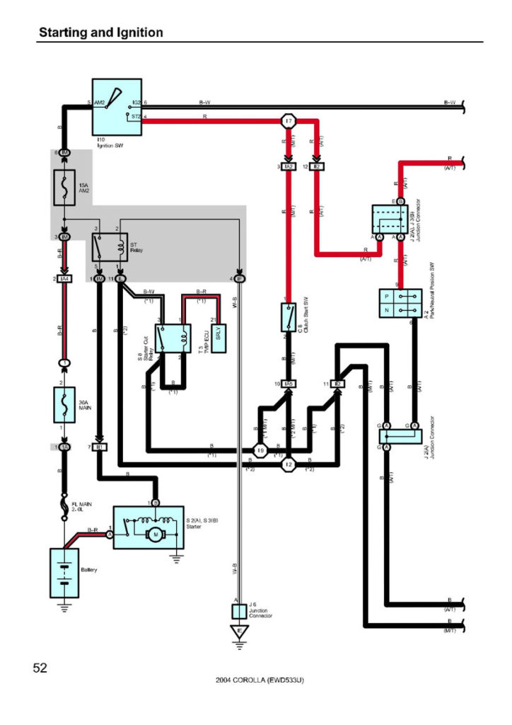
1998 Toyota Corolla Ignition Wiring Diagram – We will first look at the various kinds and functions of terminals found in the ignition switches. They include terminals for Coil, Ignition Switch, and Accessory. Once we have identified what these terminals are then we can identify the different parts in the ignition wiring. We will also discuss the roles of the Ignition switch and Coil. Then we’ll discuss the Accessory Terminals.
Terminals of ignition switch
Three switches can be found on the ignition switch. Each of these switches feeds the battery’s voltage to several different locations. The first switch powers the choke. The third switch regulates the ON/OFF switch of the ignition switch. Different manufacturers have different color codes for various conductors. This is explained in another article. OMC follows this approach. The ignition switch comes with a connector for adding a Tachometer.
Although the majority of ignition switch terminals are duplicated, the number may not match the diagram. To ensure that your wires are connected to the ignition switch you should check their continuity. A multimeter is a great tool to test the continuity. After you’re satisfied with the connection it’s time to connect the new connector. If your vehicle is equipped with an installed ignition switch the wiring diagram will differ.
Understanding how the ACC outputs connect to the auxiliary outputs in your car is vital. The ACC and IGN terminals are the default connection on the ignition switch. the START and IGN terminals are the primary connections for stereo and radio. The ignition switch is the one that controls the engine of your car. Older cars have the ignition switch terminals labeled “ACC” or “ST” (for individual magnetowires).
Terminals for Coil
Understanding the terminology is the first step in determining which type of ignition coil you have. A simple diagram of the wiring will display a range of connections and terminals, including two primary and two secondary. You need to determine the kind of coil you own by examining the voltage on the primary terminal, S1. S1 must be tested for resistance in order to determine if the coil is type A, B and/or C.
The coil’s low-tension side is to be connected to the chassis positive. This is what you see in the wiring diagram. The high-tension end provides positive direct to the sparkplugs. It is required to suppress the coil’s metallic body be connected to its chassis, but not essential. You will also see the connections between the positive and the negative coil’s terminals on the ignition wiring diagram. Sometimes, an inspection at an auto parts shop can identify a problem with the ignition wire.
The black-and-white-striped wire from the harness goes to the negative terminal. The white wire is black and connects to the negative terminal. The black wire goes to the contact breaker. You can check the connections with a pencil to remove the wires from the housing. It’s also essential to ensure that the terminals aren’t bent.
Accessory terminals

Diagrams of ignition wiring show the wires that are used in the vehicle’s power supply. There are typically four color-coded terminals that correspond to each component. Red stands for accessories, yellow represents the battery and green is for the starter solenoid. The “IGN terminal” is used to provide power to the wipers along with other operational features. The diagram shows how to connect the ACC and ST terminals to the rest of the components.
The battery is attached to the terminal named BAT. The electrical system will not start in the event that the battery isn’t connected. Additionally, the switch will not turn on without the battery. You may refer to the wiring diagram if you are not sure where the batteries of your car are located. The ignition switch and the battery are connected via accessory terminals. The BAT Terminal is connected to the Battery.
Some ignition switches include an accessory position where users can modify their outputs and control them without needing to use the ignition. Sometimes, customers want to use the auxiliary output separately from the ignition. To make use of the auxiliary output, connect the connector using the same colors as the ignition, connecting it to the ACC terminal on the switch. Although this is a fantastic feature, there’s one thing you should know. Most ignition switches come with an ACC position when your vehicle is in the ACC mode and a START position when you are in IGN.
Gallery of 1998 Toyota Corolla Ignition Wiring Diagram

Gallery of 1998 Toyota Corolla Ignition Wiring Diagram


