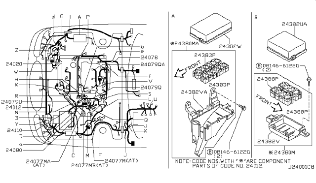
2000 Nissan Maxima Ignition Wiring Diagram – Let’s begin by examining the different types and purposes of the terminals found in the ignition switches. These terminals include the Ignition switch, the Coil as well as the Accessory. After we’ve identified the purpose of the terminals it is possible to recognize the various parts of the ignition wiring. In addition, we will discuss the functions of the Ignition switch and Coil. Then, we’ll focus to the accessory terminals.
Terminals for the ignition switch
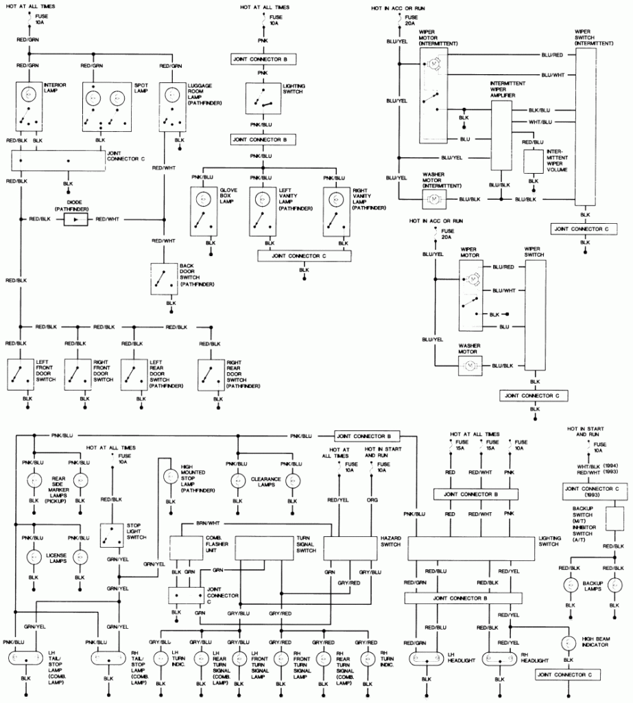
An ignition switch is composed of three switches. These are responsible for feeding the battery’s power to several destinations. The first switch supplies the choke with power, and the third switch toggles the status of the ignition switch. Different manufacturers have different colors for different conductors. This is discussed in a different article. OMC follows this system. An adapter is included on the ignition switch to allow the installation of the tonometer.
Even though some of the ignition switch terminals might not be original, the numbering of each may not be in line with the diagram. It is important to first verify the integrity of the wires to see if they are plugged into the ignition switch correctly. This can be done with a simple multimeter. When you are satisfied with the integrity of the wires, install the new connector. If you are using a factory-supplied ignition switch the wiring loom may be different from that used in your vehicle.
First, understand the differences between the ACC and the auxiliary outputs. The ACC and IGN connectors are the standard connections of your ignition switch. While the START, IGN, and ACC terminals are the primary connections to the radio or stereo, the START/IGN terminals are the most important ones. The ignition switch is responsible to turn the engine of your car on and off. In older vehicles the terminals of the ignition switch are marked with the initials “ACC”, and “ST” (for the individual magnetic wires).
Terminals for coil
To determine the type of ignition coil you need to know the step is to learn the definition of. A basic ignition wiring diagram will reveal a variety of connections and terminals, comprising two primary and two secondaries. It is essential to identify the type of coil that you own by examining the voltage at the primary terminal, called S1. S1 must also be subjected to resistance tests to determine if it’s an A or B coil.
The low-tension coil side must be connected to the chassis’ minus. This is the ground of the ignition wiring. The high-tension part is a positive connection to the sparkplugs. To prevent noise the body of the coil must be connected to the chassis. It is not necessary to connect the coil electrically. The ignition wiring diagram will also show you the connections between the positive and negative coil’s terminals. In some instances it is possible to find a malfunctioned ignition coil is identified by scanning at an auto parts store.
The black-and-white-striped wire from the harness goes to the negative terminal. The white wire is the other one. It is black with a trace, and it goes to the positive terminal. The black wire is connected to the contactbreaker. If you’re unsure of the connections between the two, try using the clip of a paperclip to remove them from the plug housing. Also, make sure to check that the terminals aren’t bent.
Accessory Terminals
Diagrams of ignition wiring illustrate the wires that are used in the power supply of the vehicle. There are generally four color-coded terminus for each component. The red color is for accessories, yellow the battery and green for the starter solenoid. The “IGN terminal” is used to power the wipers along with other operational features. The diagram shows the connections of the ACCand ST terminals.
The terminal BAT connects the battery to the charger. Without the battery the electrical system can not start. In addition, the switch will not begin to turn on. You can view the wiring diagram of your car to see where your car’s batteries are situated. The accessory terminals in your car connect to the ignition switch as well as the battery. The BAT terminal is connected to the battery.
Certain ignition switches have an independent “accessory” position, where users can manage their outputs without using the ignition. Users may wish to utilize the auxiliary output independently of the ignition. In order to use the auxiliary output, connect the connector using the same colors as ignition connecting it to the ACC terminal on the switch. This feature of convenience is fantastic however there’s a difference. The majority of ignition switches are set to be in an ACC position when the vehicle is in the ACC position, whereas they’re in the START position when the vehicle is in the IGN position.
Gallery of 2000 Nissan Maxima Ignition Wiring Diagram
Gallery of 2000 Nissan Maxima Ignition Wiring Diagram


