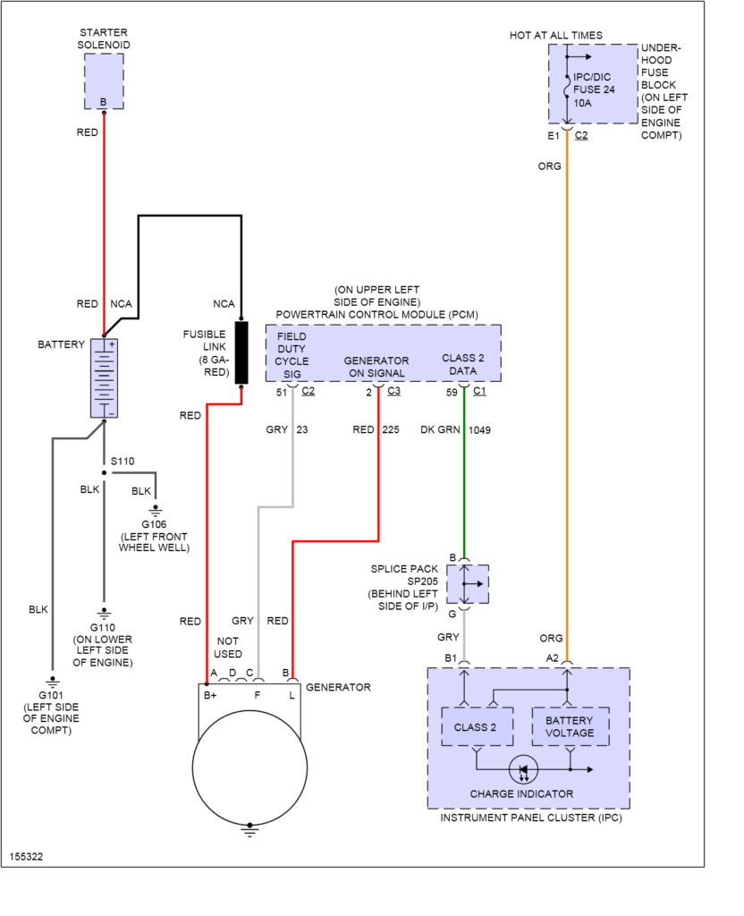
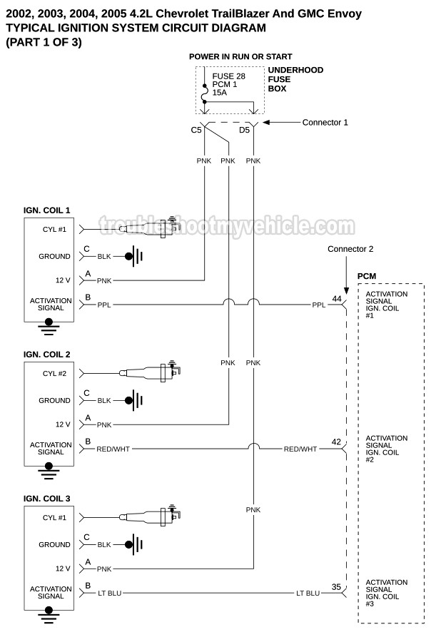
2002 Chevy Trailblazer Ignition Wiring Diagram – Let’s first look at the different terminals used on the ignition switch. These are the terminals that connect the Ignition, Coil, or Accessory. Once we know the terminals used, we can begin to recognize the various parts of the 2002 Chevy Trailblazer Ignition Wiring Diagram. Then, we will discuss the functions as well as the Coil. Following that, we will discuss the Accessory Terminals.
Terminals for ignition switch
There are three switches on an ignition switch, which feed the battery’s voltage to a variety of places. The first switch powers the choke. The second switch is responsible for the ON/OFF of the ignition switch. Different manufacturers use different color-coding methods to identify different conductors. This will be covered in a different article. OMC follows the same system. Connectors can be connected to the ignition switch in order to connect a digital tachometer.
Although some ignition switch terminals may not be original, the numbering of the terminals may not match the diagram. To ensure that your wires are correctly connected to the switch you should check their continuity. A cheap multimeter can assist you in this. Once you are satisfied that the wires are in good order, you can attach the new connector. If your vehicle has an original ignition switch supplied by the factory (or wiring loom), the wiring loom may differ from that in your vehicle.
It is important to understand how the ACC outputs and the auxiliary outputs function in order to join them. The ACC and IGN terminals are the default connections for the ignition switch. the START and IGN terminals are the primary connections to the radio and stereo. The ignition switch is the one that turns the car’s engine to and off. Older cars are equipped with ignition switch’s terminals that are labeled “ACC” or “ST” (for individual magnetowires).
Terminals for coil
The terminology used to determine the type and model of an ignition coil is the first thing. A basic ignition wiring diagram will display a range of terminals and connections comprising two primary and two secondary. The coils are equipped with a particular operating voltage. The initial step in determining which type you’re using is to test the voltage on S1, the primary terminal. It is also recommended to examine S1 for resistance to identify if it’s an A B, C, or coil.
The coil with low tension must be connected to the chassis’s plus. This is the ground in the ignition wiring diagram. The high tension side provides positive directly the spark plugs. To reduce the noise the body of the coil must be connected to the chassis. But, it’s not necessary to electrically connect. The wiring diagram of the ignition will show you how to connect the terminals of either the positive and negative coils. In certain instances, you’ll find that a malfunctioned ignition coil can be diagnosed with scanning in an auto parts store.
The black-and-white-striped wire from the harness goes to the negative terminal. The negative terminal is served by the black trace that’s joined to the white wire. The black wire connects to the contact breaker. If you’re not certain about the connection between the twowires, use an old paper clip to take them from the plug housing. It’s also crucial to make sure that the terminals don’t bend.
Accessory terminals
The ignition wiring diagrams illustrate the different wires that power the various components of the car. There are generally four color-coded terminus for each component. Red stands for accessories, yellow is for the battery and green is for the solenoid for starters. The “IGN terminal” is used to provide power to the wipers as well as other operating functions. This diagram shows how you can connect ACC and ST terminals with the rest of the components.
The terminal BAT connects the battery to the charger. The electrical system won’t start without the battery. Additionally, the switch will not turn on without the battery. It is possible to refer to your wiring diagram if you’re uncertain about where the car’s batteries are located. The ignition switch and the battery are connected through the accessory terminals. The BAT Terminal is connected to the Battery.
Certain ignition switches have an additional “accessory” position, where users can control their outputs without the ignition. Customers sometimes want the auxiliary output to be used independently from the ignition. The auxiliary output can be connected to connect the connector in the same colors as your ignition and attaching it to the ACC terminal of the switch. This is a great convenience feature, but there is one difference. A majority of ignition switches feature the ACC position when your vehicle is in the ACC mode, and a START position when the switch is in IGN.
Gallery of 2002 Chevy Trailblazer Ignition Wiring Diagram
Gallery of 2002 Chevy Trailblazer Ignition Wiring Diagram


