2004 Gmc Sierra Ignition Switch Wiring Diagram – We will first take a look at the various kinds of terminals that are found in the ignition switch. The terminals are the Ignition switch as well as the Coil along with the Accessory. When we have a clear understanding of the purpose of each terminal, we are able to identify the parts of the ignition wiring. We’ll also go over what functions are available for the Ignition switch as well as the Coil. After that, we’ll turn our attention to the Accessory terminals.
Terminals for ignition switches
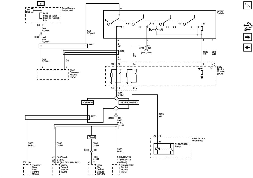
Three switches are located on the ignition switch. Each of these three switches is able to feed the battery’s voltage to several different locations. The first switch is the one that supplies power to the choke, while the second toggles the state of the switch. Different manufacturers have different colors for various conductors. This is described in a separate article. OMC utilizes this method. The ignition switch is also equipped with an option to connect a timer.
While most ignition switch terminals are duplicated, the numbers may not be consistent with the diagram. You should first check the electrical continuity to determine if they’re connected to the ignition switch in the correct way. This can be done with a simple multimeter. Once you’re satisfied with the continuity, you can place the new connector. If your vehicle has an installed ignition switch, the wiring diagram will differ.
First, understand the differences between ACC and auxiliary outputs. The ACC/IGN connections function as the default connections on the ignition switch. The START/IGN connections connect to the radio or stereo. The ignition switch is responsible for turning the engine of your car on and off. On older vehicles the terminals of the ignition switch are marked with the alphabets “ACC” and “ST” (for distinct magnet wires).
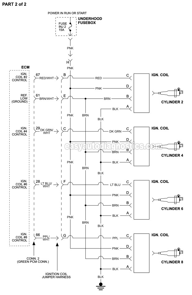
Terminals for coil
The first step in determining the kind of ignition coil is to know the terms used. In a simple diagram of the wiring for ignition there are a number of different terminals and connections, including two primary and two secondary. Each coil has a specific operating voltage. To determine which type of coil you’ve got first, you need to check the voltage at S1, the primary terminal. S1 should also be checked for resistance to determine whether it’s an A, Type B or an A coil.
The chassis’ negative needs to be connected to the low-tension side. This is the wiring diagram you will see on the wiring diagram. The high-tension end is a positive connection to the sparkplugs. For suppression purposes, the coil’s metal body is required to be connected to the chassis. But, it’s not necessary to connect the coil electrically. A wiring diagram can depict the connection between positive and negative coil terminals. There could be an issue with the ignition coil which can be identified by scanning it at an auto parts store.
The black-and-white-striped wire from the harness goes to the negative terminal. The positive terminal is connected to the white wire with the trace in black. The black wire is connected to the contact breaker. It is possible to check the connections with a paperclip to remove the wires from the housing. Make sure that the connectors don’t bend.
Accessory terminals
The ignition wiring diagrams show the various wires that are used to power the various components. Each component has four distinct colored connections. For accessories, red stands the starter solenoid’s color, yellow is for battery, and blue is for accessory. The “IGN terminal” is used to run the wipers, as well as other operating functions. The below diagram shows how to connect the ACC terminal and ST terminals to various components.
The terminal BAT is where the battery is. The electrical system can’t start without the battery. In addition, the switch will not begin to turn on. If you’re not sure where your car’s battery is located, you can look at your wiring diagram to figure out how to locate it. The accessory terminals in your car are connected to the ignition switch and the battery. The BAT terminal is connected to the battery.
Some ignition switches come with an additional “accessory position” which allows users to modify their outputs independent of the ignition. Some customers might want to use the auxiliary output separately from the ignition. To use the additional output, wire the connector using identical colors to the ignition and connect it to the ACC terminal on the switch. This option is useful, but it has one major distinction. Some ignition switches are programmed to have an ACC location when the car is in the ACC position. They’ll also be in the START mode once the vehicle is entered the IGN position.
Gallery of 2004 Gmc Sierra Ignition Switch Wiring Diagram
Gallery of 2004 Gmc Sierra Ignition Switch Wiring Diagram


