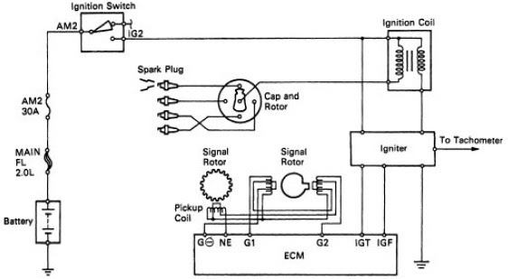
2004 Toyota Camry Ignition Coil Wiring Diagram – Let’s begin by looking at the various types of terminals on an ignition switch. These are terminals for the Ignition, Coil, or Accessory. Once we have identified what these terminals are then we can be able to identify the various parts of the ignition wiring. We’ll also discuss the functions and the Coil. Next, we’ll discuss the roles of the ignition switch and Coil.
Terminals for ignition switch
There are three different switches on the ignition switch, and they feed the battery’s voltage to various destinations. The first one supplies power to the choke whenever it is pushed. The second is the position of the ignition switch’s ON/OFF. Every manufacturer has its individual color-coding system that we’ll go over in a separate article. OMC uses this method. An adapter is included on the ignition switch to allow for the addition of the Tachometer.
While the majority of ignition switch terminals do not appear in their original configuration The numbering might not match that of the diagram. Before you plug into the ignition switch ensure that you check the continuity. This can be done with an inexpensive multimeter. Once you’re satisfied with the continuity then you can connect the new connector. The wiring loom of an ignition switch that’s supplied by the factory will be different from the one in your car.
Knowing how the ACC outputs connect to the auxiliary outputs of your car is vital. The ACC/IGN terminals function as the default connection on the ignition switch. The START/IGN terminals connect to the radio or stereo. The ignition switch switches the car’s engine on and off. The terminals for the ignition switch on older cars are labeled with the alphabets “ACC” as well as “ST” (for each magneto wires).
Terminals for Coil
To identify the kind of ignition coil, the initial step is to understand the terms. There are a variety of connections and terminals on a basic ignition wiring schematic, including two primary, as well as two secondary. The coils come with a distinct operating voltage, and the first step to determine which one you have will involve testing the voltage of S1 the main terminal. S1 must be tested for resistance in order to identify if the coil belongs to Type A, B, or C.
The coil’s low-tension component is to be connected to the chassis positively. This is the base of the wiring for ignition. The high tension side provides positive directly the spark plugs. It is required to suppress the metallic body of the coil is connected to its chassis however it isn’t essential. The wiring diagram for the ignition will show you how to connect the terminals of the positive and negative coils. It is possible to find an ignition coil problem which can be identified by scanning it in an auto parts retailer.
The black-and-white-striped wire from the harness goes to the negative terminal. The other white wire is black-colored and connects to the negative terminal. The black wire connects to the contact breaker. If you’re not certain about the connections between the twowires, use a paper clip to remove them from the housing of the plug. Be sure the terminals don’t bend.
Accessory terminals
Diagrams of ignition wiring illustrate the wires used to power the vehicle’s electrical supply. In general there are four distinct colors-coded terminals that are used for each component. Red is for accessories while yellow is the battery, while green is the solenoid for starters. The “IGN” terminal is used to turn on the car and operate the wipers, as well as other operating functions. This diagram shows how you can connect ACC and ST terminals to the rest of components.
The terminal BAT connects the battery to the charger. The electrical system won’t start if the battery isn’t connected. Furthermore, the switch won’t begin to turn on. It is possible to look up your wiring diagram to determine the location of your car’s batteries. placed. The accessory terminals in your car are connected to the battery and ignition button. The BAT Terminal is connected to the battery.
Some ignition switches come with an independent “accessory” position, where users can control their outputs with no ignition. Sometimes, users want to use an auxiliary output independent of the ignition. You can use the secondary input by connecting it to the ACC terminal. This is a great convenience feature, but there is one differentiator. The majority of ignition switches are configured to display an ACC status when the car is in either the ACC or START position.
Gallery of 2004 Toyota Camry Ignition Coil Wiring Diagram
Gallery of 2004 Toyota Camry Ignition Coil Wiring Diagram


