2007 Dodge Charger Ignition Wiring Diagram – First, we will look at the different types of terminals found on the ignition switch. They are terminals that are used for Coil, Ignition Switch, and Accessory. Once we’ve established the purpose of the terminals it is possible to recognize the various parts of the ignition wiring. Then, we will discuss what functions are available for the Ignition switch, as well as the Coil. After that, we’ll turn our attention to Accessory terminals.
Terminals for ignition switch
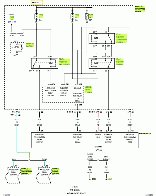
An ignition switch has three switches. They transmit the voltage of the battery to different locations. The ON/OFF position of the switch that controls the ignition is managed by the second switch, which provides the choke with power when it is pushed. Different manufacturers have different colors for different conductors. This is described in another article. OMC uses this system. The ignition switch also includes an option to connect the timer.
While most ignition switch terminals aren’t original, the numbers for each one may not be in line with the diagram. To make sure that the wires are correctly plugged in to the switch you must verify their continuity. A multimeter is a great instrument to verify the continuity. Once you’re satisfied with the connection, you can place the new connector. If your vehicle has an ignition switch that is installed the wiring diagram may differ.
To connect the ACC outputs to the auxiliary outputs on your vehicle, you have to first understand how these two connections work. The ACC terminals and IGN terminals function as the default connections to the ignition switch. The START and IGN connections are the most important connections for stereo and radio. The ignition switch acts as the engine’s on/off button. The terminals for the ignition switch on older vehicles are marked with the alphabets “ACC” and “ST” (for the individual magneto wires).
Terminals for Coil
Understanding the terminology is the initial step towards determining which type of ignition coil you have. The fundamental diagram of ignition wiring illustrates a variety of connections and terminals. There are two primary and one secondary. You need to determine the type of coil that you are using by testing the voltage at the primary terminal, called S1. S1 must be checked for resistance to identify if the coil belongs to type A, B and/or C.
The negative of the chassis must be connected to the low-tension side. This is also the ground on the diagram of ignition wiring. The high-tension side connects the spark plugs to a positive. The metal body of the coil needs to connect to the chassis for suppression purposes but is not electrically necessary. The wiring diagram for the ignition will explain how to connect the terminals of either the positive or negative coils. Sometimes, a damaged ignition coil can be detected with a scan at an auto repair shop.
The black-and-white-striped wire from the harness goes to the negative terminal. The positive terminal is connected to the white wire and the trace of black. The black wire is connected to the contact breaker. You can remove the black wire from the housing of the plug with a paper clip if you are unsure about the connections. It is also important to make sure that the terminals do not bend.
Accessory terminals
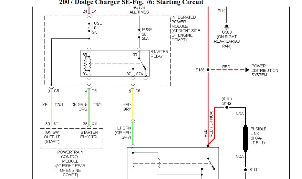
Diagrams of the ignition wiring show the wiring used to provide power to various components of the vehicle. There are generally four color-coded terminals that correspond to the respective component. Red stands for accessories, yellow is for the battery and green for the starter solenoid. The “IGN” terminal is used to start the vehicle, controlling the wipers and other functions. The diagram illustrates the connection of the ACC- and ST terminals.
The terminal BAT is the connection to the battery. The battery is vital to allow the electrical system to begin. Also, the switch won’t turn on without the battery. To find your car’s battery examine the wiring diagram. The accessory terminals in your car are connected with the battery and the ignition button. The BAT terminal is connected with the battery.
Some ignition switches come with the option of an “accessory position” which allows users to alter their outputs without the ignition. Sometimes, customers may wish to use the auxiliary output separately from the ignition. It is possible to use the additional input by connecting it to the ACC terminal. This is a convenient feature, but it has one significant differentiator. Most ignition switches are set to be in an ACC position when the vehicle is in the ACC position, while they’re set to the START position when the vehicle is in the IGN position.
Gallery of 2007 Dodge Charger Ignition Wiring Diagram
Gallery of 2007 Dodge Charger Ignition Wiring Diagram


