3 Way Ignition Switch Wiring Diagram – We will first look at the various kinds and functions of terminals found on the ignition switches. These terminals comprise the Ignition switch as well as the Coil as well as the Accessory. When we have a clear understanding of the purpose of each type of terminal, it is possible to identify the parts of the ignition wiring. Then, we will discuss the functions and the Coil. After that we will proceed to the Accessory Terminals.
Terminals for the ignition switch
The ignition switch is comprised of three switches that supply the battery’s current to various destinations. The first is used to turn on the choke through pushing it. Then, the third switch is used to control the ON/OFF position. Different manufacturers use different colors-coding systems to match the conductors. OMC utilizes this system. An adapter is included on the ignition switch that allows the installation of an tonometer.
Although the majority of ignition switch terminals do not have the original design The numbering might not be in line with the diagram. It is important to first verify the continuity of the wires to ensure that they are plugged into the ignition switch correctly. A multimeter is a good tool to check the continuity. When you’re satisfied with the integrity of your wires, you will be able to connect the new connector. If your car has an ignition switch installed, the wiring diagram will differ.
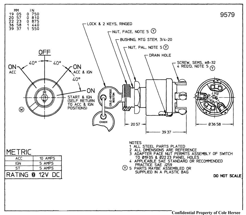
Understanding how the ACC outputs are connected to the auxiliary outputs of your car is essential. The ACC/IGN terminals act as the default connections on the ignition switch. The START/IGN connections connect to the radio or stereo. The ignition switch switches the engine of your car ON and OFF. On older cars the ignition switch’s terminals are marked with the initials “ACC” and “ST” (for the individual magnetic wires).
Terminals for coil
Understanding the terms is the initial step in finding out what kind of ignition coil you own. In a simple diagram of the wiring for ignition you’ll see various terminals and connections, including two primary and two secondary. The coils have a specific operating voltage. The first step in determining which type you’re using is to test the voltage at S1, the primary terminal. S1 should also be tested for resistance in order to identify if the coil is an A, Type B, or A coil.
The negative of the chassis must be connected to the low-tension side. This is also the ground in the diagram of ignition wiring. The high-tension side provides positive direct to the sparkplugs. The aluminum body of the coil has to be connected to the chassis to prevent it from being smothered however it’s not electrically required. The diagram for the ignition wiring will also reveal the connection of the positive and negative coil terminals. In some cases, you’ll find that the ignition coil is damaged and is identified by a scan at an auto parts store.
The black-and-white-striped wire from the harness goes to the negative terminal. The other white wire is black-colored and connects to the negative terminal. The black wire connects with the contact breaker. To verify the connections, employ a paperclip, or a pencil to remove them from the plug housing. You should also check to ensure that the terminals are not bent.
Accessory Terminals
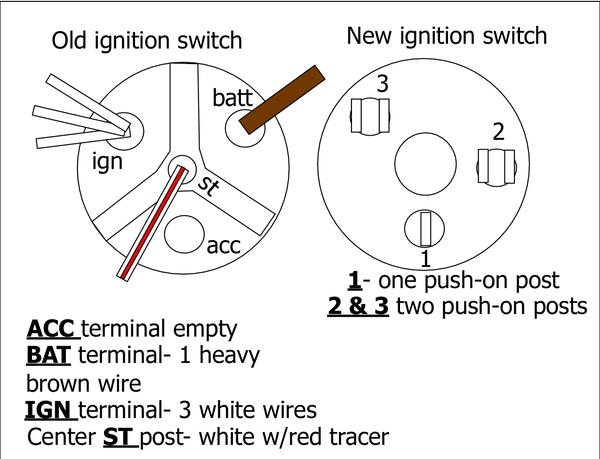
The ignition wiring diagrams show the various wires utilized for powering the different components. In general there are four distinct color-coded terminals for each component. The red color is used for accessories while yellow is the battery, while green is for the starter solenoid. The “IGN” terminal is used to start the car, controlling the wipers and various other functions. The diagram shows the connections of the ACCas well as ST terminals.
The terminal known as BAT is the location where the battery is. The electrical system cannot start without the battery. Furthermore the switch isn’t turned on. You can refer to your wiring diagram if uncertain about where the car’s batteries are located. The ignition switch as well as the battery are connected through the accessory terminals. The BAT Terminal is connected to the Battery.
Certain ignition switches come with an “accessory” setting that permits users to control their outputs without needing to turn on the ignition. Sometimes, customers may wish to use the auxiliary input separately from the ignition. For the auxiliary output to be used, wire the connector in the same color as the ignition. Then , connect it to the ACC end of the switch. Although this is a great option, there’s a thing you need to know. Most ignition switches are set to be in an ACC position when the vehicle is in the ACC position, but they’re set to the START position when the vehicle is in the IGN position.
Gallery of 3 Way Ignition Switch Wiring Diagram
Gallery of 3 Way Ignition Switch Wiring Diagram


