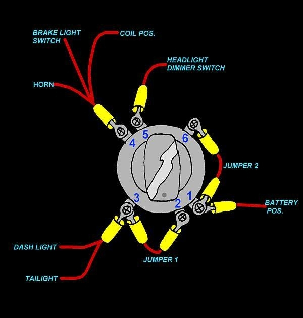
4 Wire Ignition Switch Wiring Diagram – In the beginning, we’ll examine the various types of terminals found in the ignition switch. These terminals serve for the Ignition button, Coil and Accessory. Once we know the terminals used and which ones are not, we can recognize the various parts of the 4 Wire Ignition Switch Wiring Diagram. We’ll also go over the functions for the Ignition switch as well as the Coil. Then, we’ll turn our attention to the Accessory terminals.
Terminals for ignition switches
An ignition switch has three switches. They transmit the voltage of the battery to different places. The first switch is used to power the choke through pushing it, while the second is for the ON/OFF position. Different manufacturers have their own color-coding system for different conductors that is described in a separate article. OMC follows the same system. The connector allows for the connection of a speedometer to the ignition switch.
While many ignition switch terminals may not be original, the numbers of each may not be in line with the diagram. Verify the integrity of the wires first to ensure that they’re properly connected to the ignition switch. This can be done using an inexpensive multimeter. When you’re satisfied with the continuity of the wires, then you’ll be able to install the new connector. The wiring loom used in a factory-supplied ignition system switch is distinct.
You must first understand the ways in which the ACC outputs and the auxiliary outputs function in order to join them. The ACC, IGN and START terminals are your default connection to the ignition switch. They are also the primary connections to the radio and stereo. The ignition switch is the engine’s on/off button. The terminals of the ignition switch on older cars are labeled with the initials “ACC” and “ST” (for the individual magneto wires).
Terminals for Coil
Understanding the terms is the first step towards knowing what type of ignition coil you have. In a simple diagram of the wiring for ignition there are various connections and terminals, which include two primary and two secondary. The operating voltage of every coil is different. This is why it is crucial to test the voltage at S1 (primary terminal). S1 should also undergo resistance testing to determine if it are an A or B coil.
The coil’s low-tension end must be connected to the chassis’ positive. This is also the ground in the diagram of ignition wiring. The high-tension side delivers positively directly to the spark plugs. The aluminum body of the coil needs to be linked to the chassis for suppression, but it isn’t electrically required. A wiring diagram can also show the connection between the positive and negative coils. In some instances, you’ll find that an ignition coil that is malfunctioning can be diagnosed with scanning at an auto parts shop.
The black-and-white-striped wire from the harness goes to the negative terminal. The other white wire is black and connects to the negative terminal. The black wire is connected to the contact breaker. It is possible to check the connections using a paperclip to take the wires out of the housing. You should also check to make sure that the connections aren’t bent.
Accessory terminals
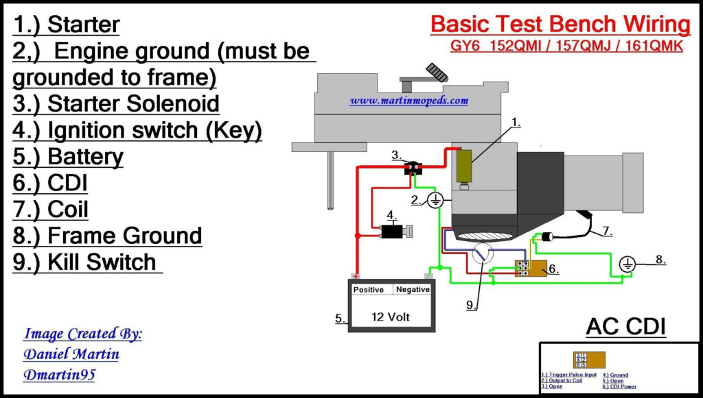
Diagrams of ignition wiring illustrate the wiring used to power the vehicle’s electrical supply. There are usually four different colors of terminals connected to each part. To identify accessories, red is for starter solenoid, yellow is for battery and blue for accessories. The “IGN” terminal is used to start the car and operate the wipers and other operating features. The diagram illustrates how you can connect ACC or ST terminals as well as the rest.
The terminal referred to as BAT is the location where the battery is. The electrical system will not start in the event that the battery isn’t connected. The switch will not turn off if the battery isn’t present. The wiring diagram will inform you where to find the battery of your car. The ignition switch as well as the battery are connected via accessory terminals. The BAT connector connects to your battery.
Certain ignition switches have an accessory position where users can alter their outputs and manage them without having to turn on the ignition. In some cases, users may want to use the auxiliary input independently of the ignition. To allow the auxiliary output to be used, plug in the connector with the same color as the ignition. Then connect it with the ACC end of the switch. Although this is a useful feature, there’s one important difference. The majority of ignition switches are set up to show an ACC status when the car is in either the ACC or START position.
Gallery of 4 Wire Ignition Switch Wiring Diagram
Gallery of 4 Wire Ignition Switch Wiring Diagram


