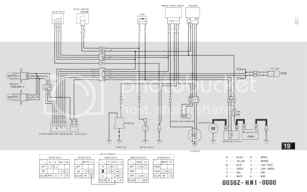
400ex Ignition Wiring Diagram – First, let’s look at the different terminals on the ignition switch. These terminals are used for the Ignition button, Coil and Accessory. After we’ve identified the terminals used then we can recognize the various parts of the 400ex Ignition Wiring Diagram. In addition, we will discuss the roles of both the Ignition Switch and Coil. The next step is to focus to the accessory terminals.
Terminals for ignition switch
An ignition switch has three different switches that direct the battery’s current to different destinations. The first switch is utilized to drive the choke by pushing it, while the third switch is used to control the ON/OFF setting. Different manufacturers use different color-coding methods for different conductors. This will be covered in a separate article. OMC follows this scheme. Connectors can be connected to the ignition switch to connect a digital tachometer.
While the majority of ignition switch terminals don’t have the original design, the numbering may not match the diagram. Check the continuity of all the wires to ensure they are correctly plugged into the ignition switches. A multimeter that is inexpensive can help you do this. After you have verified the continuity of the wires you are able to connect the connector. If your vehicle is equipped with an ignition switch installed, the wiring diagram will differ.
For connecting the ACC outputs to the auxiliary outputs of your car, you need to understand the way these two connections function. The ACC, IGN and START terminals are the primary connection to the ignition switch. They also serve as the main connections to the radio and stereo. The ignition switch acts as the engine’s off/on button. Older vehicles have ignition switch terminals marked “ACC” or “ST” (for individual magnetowires).
Terminals for Coil
The first step to determine the type of ignition coil is to understand the terms that is used. The basic ignition wiring diagram shows a number different connections and terminals. There are two primary and secondary connections. Each coil operates at a specific voltage. The first step to determine which kind you’re dealing with is to test the voltage at S1 or the primary terminal. S1 should also undergo resistance tests to determine if it are an A or B coil.
The negative of the chassis must be connected to the low-tension side. This is the wiring diagram you will see on the diagram of wiring. The high tension side provides positive directly the spark plugs. To prevent noise, the coil’s metal body must be connected to chassis. It is not required to connect electrically. There are also connections between the negative and positive coil’s terminals on an ignition wiring diagram. In some instances it is possible to find a malfunctioned ignition coil can be diagnosed with scanning at an auto parts shop.
The black-and-white-striped wire from the harness goes to the negative terminal. The positive terminal is connected to the white wire, which has a black trace. The contact breaker is linked to the black wire. To check the wires’ connections, employ a paperclip to lift them out of the housing. Make sure that the terminals do not bend.
Accessory Terminals
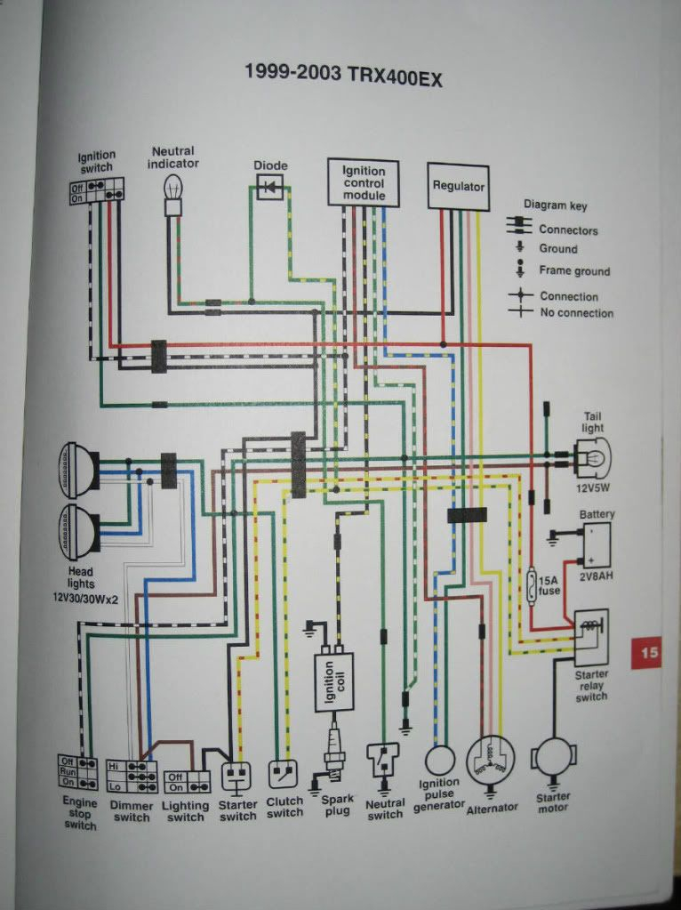
Ignition wiring diagrams depict the different wires used to power the various components. Each part has four distinct color-coded connections. The red symbol represents accessories, yellow represents the battery, and green for the starter solenoid. The “IGN” terminal can be utilized to turn on the car, turn on the wipers, as well as other functions. The diagram shows the connection between the ACCas well as ST terminals.
The terminal BAT is the connection to the battery. The battery is vital to allow the electrical system to start. A dead battery can make the switch not come on. A wiring diagram can show you the location of your car’s battery. The ignition switch is connected to the car’s battery. The BAT connector is connected to your battery.
Some ignition switches come with an additional “accessory position” that allows users to modify their outputs independent of the ignition. Some customers want the output of the auxiliary to be used independently from the ignition. It is possible to use the auxiliary input by connecting the connector to the ACC terminal. While this is an excellent feature, there’s one thing you need to know. The majority of ignition switches are set up to show an ACC status when the car is at either the ACC or START positions.
Gallery of 400ex Ignition Wiring Diagram
Gallery of 400ex Ignition Wiring Diagram


