5 Prong Ignition Switch Wiring Diagram – First, we will examine the different types of terminals on the ignition switch. These include terminals that are used for Coil, Ignition Switch, and Accessory. After we’ve identified the purpose of these terminals, we will identify the different parts in the ignition wiring. We’ll also discuss the roles of the Ignition switch and Coil. Then, we’ll focus to the accessory terminals.
Terminals for ignition switches
There are three different switches in the ignition switch, and they feed the battery’s voltage to various locations. The ON/OFF setting of the ignition switch is controlled by the first switch, which provides power to the choke whenever it is pushed. Different manufacturers have their own color-coding system for the various conductors, that is described in a separate article. OMC uses this method. Connectors can be connected to the ignition switch in order to include a digital Tachometer.
Although many ignition switch terminals don’t come in original form however, the numbers may not be in line with the diagram. It is important to first verify the electrical continuity to ensure that they are plugged into the ignition switch correctly. A multimeter is a great tool to check the continuity. After you have verified the integrity of the wires you can then install the connector. If your car is equipped with an original ignition switch supplied by the factory (or a wiring loom) the wiring loom might differ from that of your car.
Knowing how the ACC outputs are connected to the auxiliary outputs in your car is vital. The ACC terminals and IGN terminals serve as the standard connections for the ignition switch. The START and IGN connections are the most important connections for stereo and radio. The ignition switch acts as the engine’s off/on button. Older cars have the ignition switch terminals marked “ACC” or “ST” (for individual magnetowires).
Terminals for coil
To figure out the type of ignition coil, the initial step is to learn the terms. The diagram of the basic ignition wiring depicts various connections and terminals. There are two primary and one secondary. The operating voltage of every coil is different. This is why it is important to first test the voltage at the S1 (primary terminal). S1 should be checked for resistance to identify if the coil belongs to Type A, B, and/or C.
The chassis’ negative must be connected to the low-tension side. This is what is known as the ground for the wiring for ignition. The high-tension component provides the spark plugs with positive. The coil’s metal body needs to connect to the chassis to prevent it from being smothered but is not electrically required. The wiring diagram for the ignition will explain how to connect the terminals of either the positive and negative coils. Sometimes, a malfunctioning ignition coil can be detected through a scan performed at an auto repair shop.
The black-and-white-striped wire from the harness goes to the negative terminal. The negative terminal is served by the black trace that’s connected to the white wire. The black wire connects to the contactbreaker. You can remove the black wire from the plug housing with a paper clip If you’re unsure of the connections. Make sure that the connectors do not bend.
Accessory Terminals
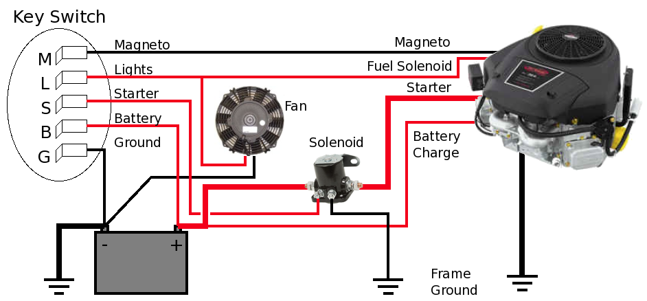
Diagrams of the ignition wiring show the wires used to provide power to various components of the vehicle. There are usually four colored terminals that correspond to the respective component. Red is used for accessories and yellow is for the battery, while green is for the starter solenoid. The “IGN” terminal can be used to start the car, operate the wipers and other features. The diagram illustrates the connection of the ACCand ST terminals.
The terminal BAT holds the battery. Without the battery the electrical system will not begin. Additionally, the switch won’t begin to turn on. It is possible to refer to your wiring diagram if unsure where your car’s batteries are. The accessory terminals in your car are connected to the ignition switch and the battery. The BAT terminal is connected to the battery.
Some ignition switches include an accessory setting where users can alter their outputs and control them without needing to use the ignition. In some cases, users may want to utilize the auxiliary input separately from the ignition. Use the secondary output by connecting it to the ACC terminal on your switch using the same colors. This is a great convenience feature however, there’s one difference. Most ignition switches are set to have an ACC position when the vehicle is in the ACC position, while they’re set to the START position when the car is in the IGN position.
Gallery of 5 Prong Ignition Switch Wiring Diagram
Gallery of 5 Prong Ignition Switch Wiring Diagram


