5 Terminal Ignition Switch Wiring Diagram – In the beginning, we’ll take a look at the various kinds of terminals that are found on the ignition switch. These include the terminals for the Ignition switch, Coil, and Accessory. When we have a clear understanding of the purpose of each terminal, it is possible to identify the various components of the ignition wiring. Then, we will discuss the functions and the Coil. Following that, we will move on to the Accessory Terminals.
Ignition switch terminals
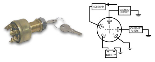
The ignition switch consists of three switches. These are responsible for feeding the battery’s power to several destinations. The first switch powers the choke. The second switch is responsible for the ON/OFF of the ignition switch. Different manufacturers use various color codes for the various conductors. This is described in a separate article. OMC utilizes this procedure. A connector can be added to the ignition switch in order to include a digital Tachometer.
While many ignition switch terminals could not be original, the numbering of the terminals may not be in line with the diagram. First, check the continuity of all the wires to ensure they are correctly connected to the ignition switches. A multimeter is an excellent tool to test the continuity. When you’re satisfied with the integrity of your wires, you will be able to connect the new connector. The wiring loom in the ignition system switch supplied by the manufacturer is different.
Knowing how the ACC outputs are connected to the other outputs inside your car is vital. The ACC and IGN connectors are the standard connections for your ignition switch. Although the START, IGN, and ACC terminals are the main connections for radios or stereo, the START/IGN terminals are the main ones. The ignition switch is responsible to turn the car’s engines on and off. Older vehicles are identified with the initials “ACC”, “ST”, (for individual magneto cables) at their ignition switch’s terminals.
Terminals for coil
To determine the type of ignition coil you need to know the step is to know the terms. You will see several connections and terminals within the basic wiring diagram for ignition, including two primary, as well as two secondary. You need to determine the kind of coil you have by testing the voltage at the primary terminal, called S1. To determine if it is a Type A, C, or B coil you should also test S1’s resistance.
The negative of the chassis must be connected to the side of low-tension. This is the ground in the ignition wiring diagram. The high-tension side supplies positively directly to the spark plugs. To reduce the noise the body of the coil must be connected to the chassis. It is not necessary to electrically connect. It is also possible to see the connections of the negative and positive coil terminals on the diagram of the ignition wiring. Sometimes, a visit to an auto parts store could detect a defective ignition wire.
The black-and-white-striped wire from the harness goes to the negative terminal. The terminal for the negative is served by the black trace that’s attached to the white wire. The black wire goes to the contact breaker. It is possible to check the connections using a paperclip to take the wires out from the housing. It’s also crucial to make sure that the terminals aren’t bent.
Accessory terminals
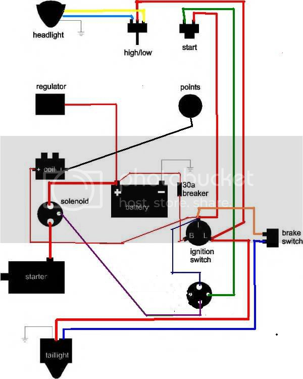
Diagrams of ignition wiring show the wires that provide power to various components of the car. There are usually four different colored terminals for each component. Red stands for accessories, yellow is for the battery and green is for the solenoid for starters. The “IGN” terminal allows you to start the car, manage the wipers, or any other operation features. This diagram shows how to connect ACC and ST terminals with the rest of the components.
The terminal BAT connects the battery to the charger. The battery is vital to allow the electrical system to get started. Additionally, the switch will not be able to turn on without the battery. To find your car’s battery examine the wiring diagram. The accessory terminals of your car are connected with the battery and ignition button. The BAT terminal connects to the battery.
Certain ignition switches come with an accessory setting where users can alter their outputs as well as control them without having to turn on the ignition. Customers sometimes want the output of the auxiliary to be used independently from the ignition. The auxiliary output could be utilized by wiring the connector in the same colors as your ignition and attaching it to the ACC terminal of the switch. Although this is a fantastic feature, there’s something you need to know. A majority of ignition switches feature the ACC position when your vehicle is in ACC mode and a START mode when it is in IGN.
Gallery of 5 Terminal Ignition Switch Wiring Diagram
Gallery of 5 Terminal Ignition Switch Wiring Diagram


