65 Mustang Ignition Wiring Diagram – The first step is to take a look at the different types of terminals that are used in the ignition switch. These are the terminals for the Ignition, Coil, or Accessory. When we have a clear understanding of the purpose of each terminal, we can then identify the various components of the ignition wiring. We’ll also go over the functions of the Ignition switch and Coil. Following that, we’ll shift our attention to Accessory terminals.
Terminals for ignition switch
An ignition switch is made up of three switches. They are the ones that supply the battery’s power to several places. The first switch supplies the choke with power when it is pushed. The third is the position of the ignition switch’s ON/OFF. Different manufacturers have distinct color-coding systems that correspond to the conductors. OMC utilizes this system. An adapter is included on the ignition switch, allowing the addition of an tachometer.
Although the majority of ignition switch terminals don’t carry an original number, they might have a different number. Check the electrical continuity to determine if they’re connected to the ignition switch correctly. This can be accomplished using a cheap multimeter. Once you’ve verified that the wires are in good condition, you are able to install the connector. The wiring loom in an ignition system switch that is supplied by the manufacturer is different.
Before connecting the ACC outputs to the auxiliary outputs of your car it is crucial to understand the basics of these connections. The ACC and IGN connectors are the standard connections of your ignition switch. The START, IGN, and ACC terminals are the main connections for radios or stereo, the START/IGN terminals are the primary ones. The ignition switch switches the engine of your car ON and off. On older cars, the ignition switch terminals are identified with the alphabets “ACC”, and “ST” (for the individual magnetic wires).
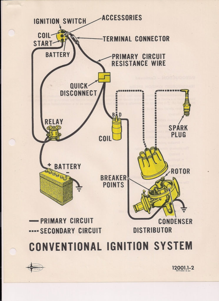
Terminals for coil
The first step in determining the type of ignition coil is to understand the terms employed. A basic ignition wiring layout will reveal a variety of connections and terminals. Each coil has an operating voltage. The first step to determine which kind you’re dealing with is to test the voltage of S1 or the primary terminal. S1 must be checked for resistance to determine if the coil belongs to type A, B and/or C.
The chassis’ negative needs to be connected to the low-tension side. This is also the ground on the diagram of the ignition wiring. The high-tension end supplies positive direct to the sparkplugs. It is required for suppression purposes that the body of the coil’s metal be connected to its chassis however, it is not necessary. It is also possible to see the connections between the negative and positive coil terminals on the ignition wiring diagram. In some cases you’ll discover that an ignition coil that is malfunctioning is identified by scanning at an auto parts shop.
The black-and-white-striped wire from the harness goes to the negative terminal. Positive terminal receives a second white wire, which has a black trace. The contact breaker is linked to the black wire. It is possible to check the connections with a paperclip to take the wires out of the housing. It’s also crucial to ensure that the terminals do not bend.
Accessory terminals
The wiring diagrams of the ignition illustrate the different wires used to power the various components of the car. Each component is equipped with four distinct color-coded connections. The red symbol represents accessories, yellow represents the battery and green for the solenoid for starters. The “IGN” terminal is used to turn on the car , and also to operate the wipers and other operating features. The diagram shows how to connect ACC or ST terminals and the rest.
The terminal called BAT is where the battery is connected. Without the battery the electrical system will not get started. Additionally, the switch will not start without the battery. If you’re not sure of the location of your car’s battery situated, you can look at the wiring diagram of your car to determine the best way to find it. The accessory terminals in your car are connected with the battery and ignition button. The BAT connector connects to your battery.
Some ignition switches come with the option of an “accessory position” which allows users to modify their outputs independent of the ignition. Users may wish to utilize the auxiliary output in addition to the ignition. It is possible to use the auxiliary input by connecting it to the ACC terminal. This convenience feature is great however there’s a distinction. Many ignition switches can be set to have an ACC position once the car has moved into the ACC position. They also will be in the START mode after the vehicle has been entered the IGN position.
Gallery of 65 Mustang Ignition Wiring Diagram
Gallery of 65 Mustang Ignition Wiring Diagram


