69 Mustang Ignition Wiring Diagram – Let’s begin by examining the different kinds and functions of terminals that are found on the ignition switches. These include the terminals that are for the Ignition switch, Coil, and Accessory. After we’ve established the purpose of these terminals are used for, we will proceed to determine the various parts of the 69 Mustang Ignition Wiring Diagram. We’ll also go over the roles of the Ignition switch as well as the Coil. Then we’ll discuss the Accessory Terminals.
The terminals are for ignition switches.
There are three different switches on an ignition switch that feed the battery’s voltage to a variety of places. The first is utilized to turn on the choke by pushing it. Then, the third switch is used to control the ON/OFF setting. Different manufacturers use different colors for various conductors. This is explained in another article. OMC uses this method. The ignition switch also includes an adapter for the addition of the timer.
Even though some of the ignition switch terminals might not be original, the numbers of each may not be in line with the diagram. Verify the integrity of the wires first to ensure they’re properly connected to the ignition switch. This can be accomplished with a simple multimeter. Once you’re satisfied about the continuity of the wires, then you’ll be able to connect the new connector. The wiring loom of the ignition system switch supplied by the manufacturer is distinct.
Understanding how the ACC outputs connect to the other outputs in your car is vital. The ACC, IGN and START terminals are the default connections to the ignition switch. They also serve as the main connections to the radio and stereo. The ignition switch turns the car’s engine on and OFF. The terminals for the ignition switch on older vehicles are marked with the letters “ACC” and “ST” (for the individual magneto wires).
Terminals for coil
Understanding the terms is the first step in finding out what kind of ignition coil you have. The diagram of the basic ignition wiring shows a number different connections and terminals. There are two primary and one secondary. It is essential to identify the kind of coil you are using by testing the voltage at the primary terminal, S1. It is also recommended to check S1 for resistance in order to identify if it’s a Type A, B, or C coil.
The negative of the chassis must be connected to the side of low-tension. It is also the ground in an ignition wiring diagram. The high-tension supply delivers the spark plugs with positive electricity directly. It is required to suppress the body of the coil’s metal be connected to the chassis, however it isn’t essential. The wiring diagram for ignition will also outline the connection of the positive coil’s terminals. In some instances, you’ll find that the ignition coil is damaged and is identified by scanning at an auto parts store.
The black-and-white-striped wire from the harness goes to the negative terminal. The terminal for the negative is served by the black trace attached to the white wire. The black wire connects to the contactbreaker. To verify the connection, use a paperclip or a pencil to remove them of the housing for the plug. Make sure the terminals aren’t bent.
Accessory terminals
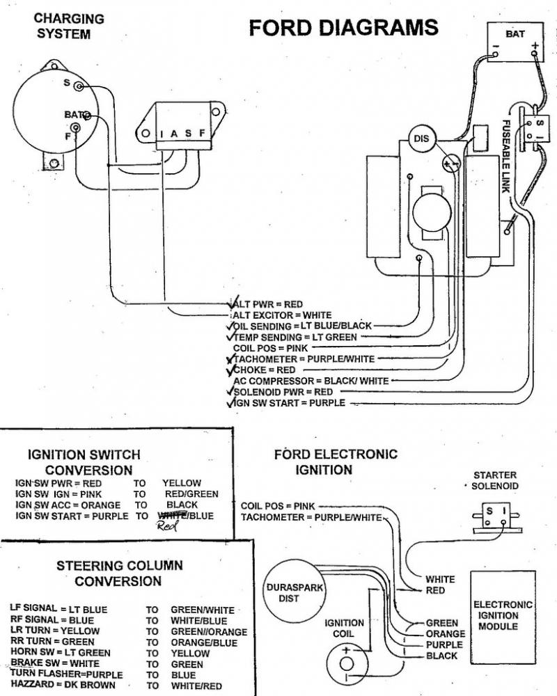
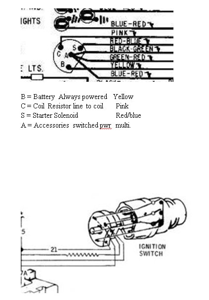
Ignition wiring diagrams show the various wires utilized to power the vehicle’s various parts. There are usually four colors-coded terminus of each part. The accessories are red while the battery is yellow, the starter solenoid green. The “IGN terminal” is used to power the wipers and other operating functions. This diagram shows how you can connect ACC and ST terminals to the other components.
The terminal called BAT is where the battery is connected. Without the battery the electrical system can not get started. A dead battery can cause the switch to stop turning on. It is possible to view your wiring diagram to figure out the location of your car’s batteries. placed. The ignition switch is linked to the car’s battery. The BAT terminal is connected to the battery.
Some ignition switches come with an additional “accessory” position, where users can control their outputs without using the ignition. Customers sometimes want an auxiliary output that can be operated independently of the ignition. You can utilize the auxiliary input by connecting it to the ACC terminal. This is a useful option, but there’s an important difference. Many ignition switches can be programmed to have an ACC location when the car has been moved into the ACC position. They also will be in START mode after the vehicle has been entered the IGN position.
Gallery of 69 Mustang Ignition Wiring Diagram
Gallery of 69 Mustang Ignition Wiring Diagram


