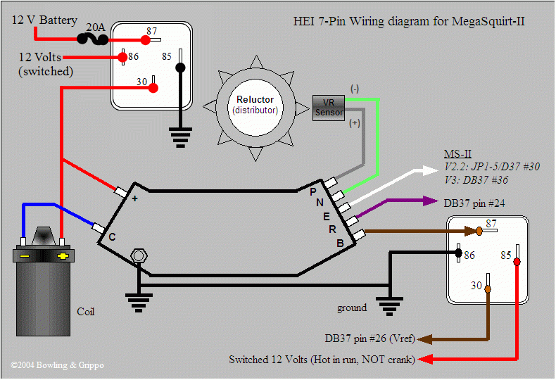
7 Pin Ignition Module Wiring Diagram – Let’s first examine the different types and purposes of the terminals in the ignition switches. These terminals are used for the Ignition button, Coil and Accessory. Once we have established what these types of terminals are then we can determine the various parts of the 7 Pin Ignition Module Wiring Diagram. We will also talk about the functions as well as the Coil. Following that, we’ll shift our attention to the Accessory terminals.
Terminals of ignition switch
The ignition switch is comprised of three separate switches that feed the battery’s power to various locations. The first switch provides power to the choke, while the second switch controls the ON/OFF status of the ignition switch. Each manufacturer has their own color-coding system, which we’ll discuss in a subsequent article. OMC uses this method. A connector is also included inside the ignition switch to allow attaching an to a tachometer.
While many ignition switch terminals do not appear in their original configuration The numbering might not be in line with the diagram. Before you plug in the ignition switch, be sure to test the continuity. This can be done using a simple multimeter. Once you are satisfied with the continuity of the wires you can install the new connector. The wiring loom used for an ignition switch that is supplied by the manufacturer will differ from the one you have in your vehicle.
To connect the ACC outputs to the auxiliary outputs of your vehicle, you have to understand the way these two connections function. The ACC, IGN and START terminals are the default connection to the ignition switch. They also function as the main connections to the radio and stereo. The ignition switch operates the engine’s switch to turn off or on. The terminals of the ignition switch on older cars are labeled with the initials “ACC” and “ST” (for the individual magneto wires).
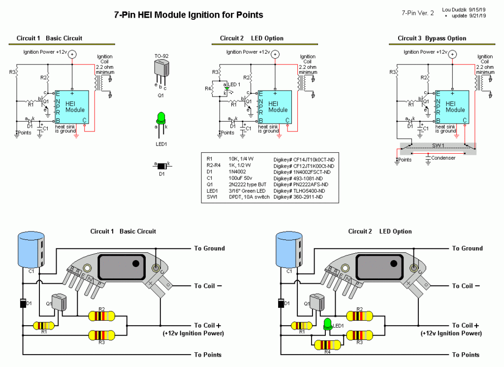
Terminals for coil
Understanding the terminology that is used is the first step to determining what kind of ignition coil to choose. An ignition wiring diagram will display a range of terminals and connections including two primary and two secondary. Each coil operates at a specific voltage. The first step to determine which kind you’re dealing with is to test the voltage of S1 or the primary terminal. S1 must also be inspected for resistance in order to identify if it’s an A, Type B or A coil.
The negative end of the chassis must be connected to connect to the coil’s lower-tension end. This is what’s called the ground in the wiring diagram for ignition. The high-tension side is a positive connection to the sparkplugs. To prevent noise the body of the coil must be connected to the chassis. It is not necessary to electrically connect. The wiring diagram will also illustrate the connection between the positive and negative coil terminals. Sometimes, a malfunctioning ignition coil can be identified by a scan done at an auto parts shop.
The black-and-white-striped wire from the harness goes to the negative terminal. The positive terminal is connected to the white wire and the trace in black. The contact breaker is attached to the black wire. To verify the connections, employ a paperclip, or a pencil to lift them out from the plug housing. Check that the terminals aren’t bent.
Accessory terminals
The diagrams for ignition wiring depict the wires used to power the vehicle’s electrical supply. There are generally four colors-coded terminus of each part. Red stands for accessories, yellow for the battery, and green for the starter solenoid. The “IGN” terminal is used to start the car, operate the wipers, as well as other functions. The diagram shows how to connect the ACC and ST terminals to the other components.
The terminal BAT holds the battery. The electrical system won’t start when the battery isn’t connected. Additionally, the switch won’t start. You may refer to the wiring diagram if you are uncertain about where the car’s batteries are located. The accessory terminals of your car are connected with the battery and ignition button. The BAT connector connects to your battery.
Certain ignition switches have an accessory setting where users can adjust their outputs and manage them without needing to use the ignition. Some customers may prefer to use the auxiliary output separately from the ignition. The auxiliary output could be connected by wiring the connector in the same colors as the ignition, and then connecting it to the ACC terminal of the switch. This feature of convenience is fantastic, but there is one distinction. A lot of ignition switches can be set to have an ACC location when the car is in the ACC position. They also will be in START mode when the vehicle has moved into the IGN position.
Gallery of 7 Pin Ignition Module Wiring Diagram
Gallery of 7 Pin Ignition Module Wiring Diagram


