72 C10 Ignition Switch Wiring Diagram – First, we will examine the various types of terminals in the ignition switch. They are terminals for Coil, Ignition Switch, and Accessory. After we’ve identified the purpose of the terminals we can recognize the various parts of the ignition wiring. We’ll also go over the functions for the Ignition switch as well as the Coil. We will then discuss the functions of the Ignition switch and Coil.
Terminals for ignition switch
Three switches are found on the ignition switch. Each of these switches is able to feed the battery’s voltage to various locations. The first switch powers the choke. The second switch controls the ON/OFF function of the ignition switch. Different manufacturers utilize their own color-coding method for the different conductors, that is described in a separate article. OMC uses this method. An adapter is included on the ignition switch that allows for the addition of a Tachometer.
Even though most ignition switch terminals don’t have an original number, they might be equipped with a different number. The first step is to check the continuity of each wire to ensure that they are properly plugged into the ignition switches. This can be checked with a simple multimeter. After you’re sure that the wires are in good order, you can attach the new connector. The wiring loom in a factory-supplied ignition system switch is different.
To connect the ACC outputs to the auxiliary outputs on your car, you need to first understand the way these two connections function. The ACC terminals and IGN terminals function as the default connections to your ignition switch. The START and IGN connections are the primary connections for radio and stereo. The ignition switch is accountable to turn the engine of your car on and off. On older vehicles the terminals of the ignition switch are identified with the initials “ACC” as well as “ST” (for the individual magnet wires).
Terminals for coil
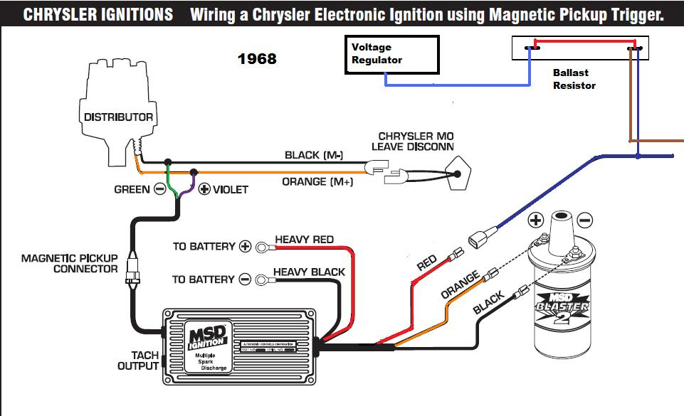
Understanding the terminology utilized is the initial step in determining the kind of ignition coil you need. The diagram of the basic ignition wiring depicts various connections and terminals. There are two primary and secondary connections. It is essential to identify the type of coil that you have by testing the voltage at the primary terminal S1. S1 must be tested for resistance in order to determine if the coil belongs to type A, B and/or C.
The low-tension end of the coil needs to be connected to the chassis”negative. It is also the ground for the diagram of ignition wiring. The high-tension component provides the spark plugs with positive. The coil’s metal body needs to be connected to the chassis for suppression purposes, but it is not electrically necessary. The wiring diagram will also show the connection between the positive and negative coils. In some instances, you’ll find that an ignition coil that is malfunctioning is easily identified with scanning at an auto parts store.
The black-and-white-striped wire from the harness goes to the negative terminal. Positive terminal gets the second white wire, which is black in its trace. The black wire is connected to the contact breaker. You can examine the connections with a paperclip to take the wires out of the housing. Be sure that you don’t bend the connectors.
Accessory terminals
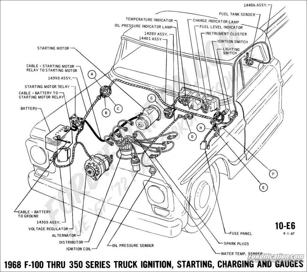
Ignition wiring diagrams show the different wires that are used to power the car’s various components. Each component is equipped with four distinct color-coded connections. The red color represents accessories, yellow represents the battery and green for the starter solenoid. The “IGN terminal is used for starting the car, operating the wipers and other functions. The diagram shows the connection between the ACCas well as ST terminals.
The battery is connected to the terminal whose name is BAT. The electrical system won’t start if the battery isn’t connected. The switch also won’t start without the battery. It is possible to look up your wiring diagram to figure out where the batteries of your car are placed. The accessory terminals of your car connect to the ignition switch, as well as the battery. The BAT terminal connects to the battery.
Certain ignition switches have an accessory position where users can adjust their outputs and control them without needing to use the ignition. Users may wish to utilize the auxiliary output in addition to the ignition. You can use the secondary output by connecting it to the ACC terminal on your switch with the same colors. Although this is a fantastic option, there’s a thing you need to know. The majority of ignition switches have an ACC position when the vehicle is in ACC however, they will be at the START position when the car is in IGN.
Gallery of 72 C10 Ignition Switch Wiring Diagram
Gallery of 72 C10 Ignition Switch Wiring Diagram


