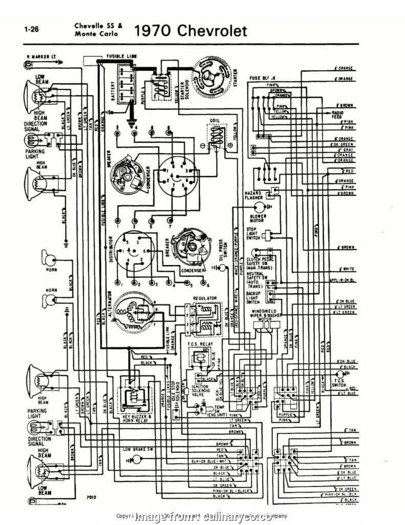
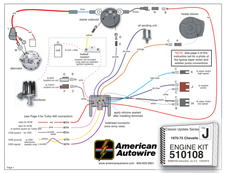
72 Chevelle Ignition Switch Wiring Diagram – Let’s begin by examining the different kinds and functions of terminals that are found in the ignition switches. These terminals are for the Ignition button, Coil and Accessory. After we’ve identified the terminals used, we can begin to recognize the various parts of the 72 Chevelle Ignition Switch Wiring Diagram. We’ll also discuss the functions of the Ignition switch and Coil. Then, we’ll turn our attention to Accessory terminals.
Terminals for ignition switch
The ignition switch has three switches. They feed the voltage of the battery to different locations. The first switch provides power to the choke, while the second toggles the ON/OFF state of the switch. Different manufacturers have distinct color-coding systems that correspond to the conductors. OMC uses the same method. Connectors can be attached to the ignition switch in order to add an electronic tachometer.
While most ignition switch terminals are not original, the numbering for each might not be consistent with the diagram. To ensure that your wires are correctly connected to the ignition switch you must verify their continuity. A multimeter is a great tool to check the continuity. After you have verified the integrity of the wires you can connect the connector. The wiring loom for the ignition switch supplied by the factory will be different from the one that you have in your car.
Understanding how ACC outputs are connected to the auxiliary outputs of your car is vital. The ACC and IGN connectors are the standard connections of your ignition switch. Although the START, IGN, and ACC terminals are the primary connections for the radio or stereo, the START/IGN terminals are the primary ones. The ignition switch is the engine’s switch to turn off or on. On older vehicles the ignition switch’s terminals are identified with the initials “ACC” and “ST” (for the individual magnetic wires).
Terminals for coil
Understanding the terms is the first step to knowing what type of ignition coil you’ve got. There are a variety of connections and terminals on the basic wiring diagram for ignition, including two primary, as well as two secondary. You need to determine the kind of coil you are using by testing the voltage on the primary terminal S1. You should also test S1 for resistance to identify if it’s a Type A B, C, or coil.
The coil with low tension must be connected at the chassis’ minus. This is what you see in the wiring diagram. The high-tension part connects the spark plugs to a positive. To reduce the noise the body of the coil must be connected to the chassis. However, it is not necessary to connect the coil electrically. It is also possible to see the connections of the positive and the negative coil terminals on the diagram of the ignition wiring. It is possible to find an issue with your ignition coil that can be easily diagnosed by looking it up at an auto parts retailer.
The black-and-white-striped wire from the harness goes to the negative terminal. The positive terminal also receives the second white wire, which is black in its trace. The black wire goes to the contact breaker. To confirm the connections, employ a paperclip, or a pencil to lift them out of the housing for the plug. Make sure that the connectors do not bend.
Accessory terminals
The ignition wiring diagrams show the different wires used for powering the various components. There are usually four color-coded terminus for each component. Red is used for accessories while yellow is the battery, and green is for the starter solenoid. The “IGN terminal lets you start your car, operate the wipers or other functions. The diagram shows the connection of the ACCas well as ST terminals.
The battery is connected to the terminal named BAT. The electrical system cannot begin without the battery. Additionally the switch isn’t turned on. The wiring diagram will tell the location of your car’s battery. The ignition switch is linked to the car’s battery. The BAT terminal is connected to the battery.
Some ignition switches have the “accessory” setting that permits users to control their outputs without needing to turn on the ignition. Sometimes, customers may wish to use the auxiliary input separately from the ignition. The auxiliary output is used by wiring the connector with the same color as your ignition, and then connecting it to the ACC terminal of the switch. This is a convenient feature however it does have one significant difference. Many ignition switches can be configured to be in an ACC position when the vehicle has been moved into the ACC position. They’ll also be in START mode after the vehicle has been entered the IGN position.
Gallery of 72 Chevelle Ignition Switch Wiring Diagram
Gallery of 72 Chevelle Ignition Switch Wiring Diagram


