93 Nissan D21 Ignition Wiring Diagram – Let’s first examine the various terminals on the ignition switch. These include the terminals that are for the Ignition switch, Coil, and Accessory. Once we know the terminals that are utilized, we can begin to identify the different components of the 93 Nissan D21 Ignition Wiring Diagram. We’ll also discuss the functions as well as the Coil. Then, we’ll turn our attention to Accessory terminals.
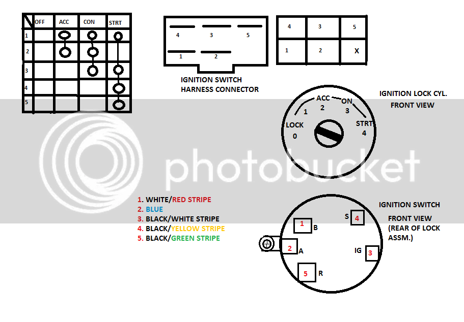
Terminals for the ignition switch
An ignition switch is made up of three different switches. They are responsible for supplying the battery’s energy to various destinations. The first switch supplies power to the choke whenever pushed, and the second is the position of the ignition switch’s ON/OFF. Different manufacturers have distinct colour-coding systems that correspond to the conductors. OMC utilizes this method. A connector can be added to the ignition switch in order to include an electronic Tachometer.
While most ignition switch terminals are not original, the numbering for each may not match the diagram. The first step is to check the continuity of all wires to ensure that they are properly connected to the ignition switches. You can check this using an inexpensive multimeter. Once you’re satisfied about the continuity of your wires, you will be able to install the new connector. If you have a factory-supplied ignition switch, the wiring loom is different from the one you have in your car.
To connect the ACC outputs to the auxiliary outputs of your car, you need to understand how these two connections work. The ACC and IGN terminals are the default connection on your ignition switch. the START and IGN terminals are the primary connections for the radio and stereo. The ignition switch is the one that turns the engine of your car to and off. Older cars are equipped with ignition switch terminals marked “ACC” or “ST” (for individual magnetowires).
Terminals for coil
The terms used to define the model and type of an ignition coil is the first thing. You will see several connections and terminals within the basic wiring diagram for ignition that include two primary and two secondary. The coils are equipped with a particular operating voltage, and the first step in determining which type you’ve got is to check the voltage at S1, the main terminal. S1 should also be tested for resistance to determine whether it’s an A, Type B or A coil.
The chassis’ negative end should be connected to the coil’s low-tension side. This is exactly what you can see on the wiring diagram. The high-tension supply delivers the spark plugs with positive electricity directly. For suppression purposes, the coil’s metal body is required to be connected to the chassis. It is not required to connect electrically. It is also possible to see the connections of the positive and negative coil’s terminals on the diagram of the ignition wiring. In certain cases scanning your local auto parts shop will help identify the malfunctioning ignition coils.
The black-and-white-striped wire from the harness goes to the negative terminal. The negative terminal is served by the trace in black that’s joined to the white wire. The black wire connects to the contact breaker. It is possible to remove the black wire from the housing of the plug with a paper clip in case you are uncertain about the connections. It’s also essential to ensure that the terminals aren’t bent.
Accessory terminals
The ignition wiring diagrams illustrate the various wires used to power the car’s various components. Each component is equipped with four distinct color-coded connections. The red color is used for accessories, yellow is for the battery, and green is for the starter solenoid. The “IGN” terminal allows you to start your car, operate the wipers, and any other features that operate. The diagram demonstrates how to connect the ACC and ST terminals to the rest of the components.
The terminal called BAT is the place where the battery is. The electrical system cannot begin without the battery. A dead battery could cause the switch to stop turning on. You can refer to your wiring diagram if you’re not sure where the batteries of your car are. The accessory terminals of your car are connected with the battery as well as the ignition button. The BAT terminal connects to the battery.
Some ignition switches are equipped with an accessory position. This allows users to connect their outputs to a different place without the ignition. Sometimes, customers want to utilize an auxiliary output that is separate from the ignition. To make use of the additional output, wire the connector with the same colors as the ignition, connecting it to the ACC terminal on the switch. While this is an excellent feature, there’s something to be aware of. Most ignition switches come with an ACC position when your car is in ACC mode and a START position when the switch is in IGN.
Gallery of 93 Nissan D21 Ignition Wiring Diagram
Gallery of 93 Nissan D21 Ignition Wiring Diagram


