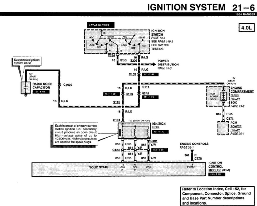
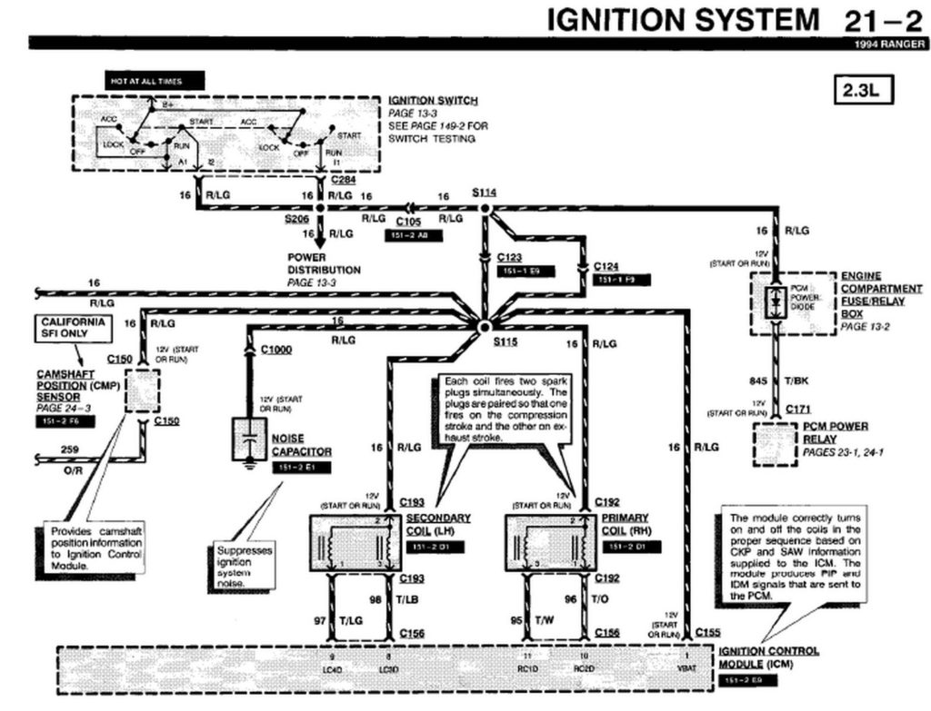
94 Ford Ranger Ignition Switch Wiring Diagram – First, let’s examine the various terminals that are used in the ignition switch. These include the terminals that are for the Ignition switch, Coil, and Accessory. Once we have identified which terminals are used and which ones are not, we can recognize the various parts of the 94 Ford Ranger Ignition Switch Wiring Diagram. We will also discuss the roles of the Ignition switch and Coil. We will then turn our attention towards the accessories terminals.
Terminals for ignition switch
An ignition switch is comprised of three switches. They supply the battery’s voltage to different locations. The first one is used to drive the choke through pushing it, while another switch controls the ON/OFF setting. Different manufacturers use their own color-coding systems for different conductors that is described in a separate article. OMC follows the same system. The ignition switch comes with an option to connect the Tachometer.
While most ignition switch terminals are not authentic, the numbering of each may not match the diagram. Check the electrical continuity to ensure that they are plugged into the correct ignition switch. You can check this using an inexpensive multimeter. Once you’ve verified the integrity of the wires you can then install the connector. The wiring loom of an ignition switch that is factory-supplied will be different than the one that you have in your car.
To connect the ACC outputs to the auxiliary outputs on your car, you need to understand how these two connections work. The ACC and IGN connectors are the standard connections for your ignition switch. Although the START, IGN, and ACC terminals are the primary connections for radios or stereo, the START/IGN connections are the main ones. The ignition switch’s function is to turn the car’s engines on and off. In older vehicles the terminals of the ignition switch are marked with the letters “ACC” and “ST” (for distinct magnetic wires).
Terminals for coil
The terminology used to determine the type and model of the ignition coil is the first thing. You’ll see a number of connections and terminals within the basic wiring diagram for ignition that include two primary as well as two secondary. The coils come with a distinct operating voltage, and the first step in determining which type you’re using is to test the voltage on S1, the primary terminal. It is also recommended to test S1 for resistance in order to determine if it’s an A or B coil.
The chassis’ negative must be connected to connect to the coil’s lower-tension end. This is what’s called the ground in the wiring diagram for ignition. The high-tension supply delivers positive directly to spark plugs. The coil’s aluminum body needs to be linked to the chassis for suppression but isn’t required. The wiring diagram for ignition will also indicate the connections of the positive coil terminals. Sometimes, a visit to an auto parts shop can diagnose a malfunctioning ignition wire.
The black-and-white-striped wire from the harness goes to the negative terminal. The other white wire is black and connects to the negative terminal. The black wire connects to the contact breaker. To check the wires’ connections, use a paperclip and lift them off the housing. It’s also crucial to make sure that the terminals don’t bend.
Accessory terminals
Ignition wiring diagrams show the various wires used to power the car’s various components. There are usually four colored terminus lines for each component. Red is for accessories while yellow is the battery, while green is for the starter solenoid. The “IGN” terminal can be used to start the car , and also to operate the wipers and other operating functions. This diagram demonstrates how to connect ACC and ST terminals to the other components.
The terminal BAT connects the battery to the charger. The electrical system won’t start in the event that the battery isn’t connected. In addition the switch isn’t turned on. You can refer to your wiring diagram if you’re uncertain about where the car’s batteries are. The ignition switch is linked to the car’s battery. The BAT terminal is connected to the battery.
Some ignition switches include an accessory position where users can alter their outputs as well as control them without the need to use the ignition. Users may wish to use the auxiliary output in addition to the ignition. In order to use the auxiliary output, connect the connector in identical colors to the ignition connecting it to the ACC terminal on the switch. This is an excellent option, but there’s one important distinction. A lot of ignition switches can be programmed to have an ACC location when the car has been moved into the ACC position. They also will be in START mode after the vehicle has been moved into the IGN position.
Gallery of 94 Ford Ranger Ignition Switch Wiring Diagram
Gallery of 94 Ford Ranger Ignition Switch Wiring Diagram


