95 Honda Civic Ignition Switch Wiring Diagram – We will first take a look at the different kinds of terminals on the ignition switch. They include terminals for the Ignition switch, Coil, and Accessory. Once we’ve determined the function of these terminals, we can identify the various parts of the ignition wiring. We’ll also go over the functions for the Ignition switch as well as the Coil. We’ll then turn our attention on the accessory terminals.
Terminals for the ignition switch
There are three switches on an ignition switch, which provide the battery’s voltage to several different places. The first switch powers the choke. The second switch is responsible for the ON/OFF of the ignition switch. Different manufacturers have different color-coding systems that correspond to the conductors. OMC uses the same method. The ignition switch also includes a connector for adding a tachometer.
Although most ignition switch terminals can be duplicated, the number may not be consistent with the diagram. Verify the continuity of the wires first to make sure they are correctly plugged in the ignition switch. This can be accomplished with a simple multimeter. After you’re happy with the continuity of the wires, then you’ll be able install the new connector. If your car has an original factory-supplied ignition switch (or wiring loom) the wiring loom might differ from the one in your car.
It is essential to know the way that ACC outputs and the auxiliary outputs work in order to connect them. The ACC and IGN terminals are the default connections on your ignition switch. the START and IGN terminals are the main connections for the stereo and radio. The ignition switch is the one that turns the car’s engine to and off. Older vehicles have ignition switch’s terminals that are labeled “ACC” or “ST” (for individual magnetowires).
Coil terminals
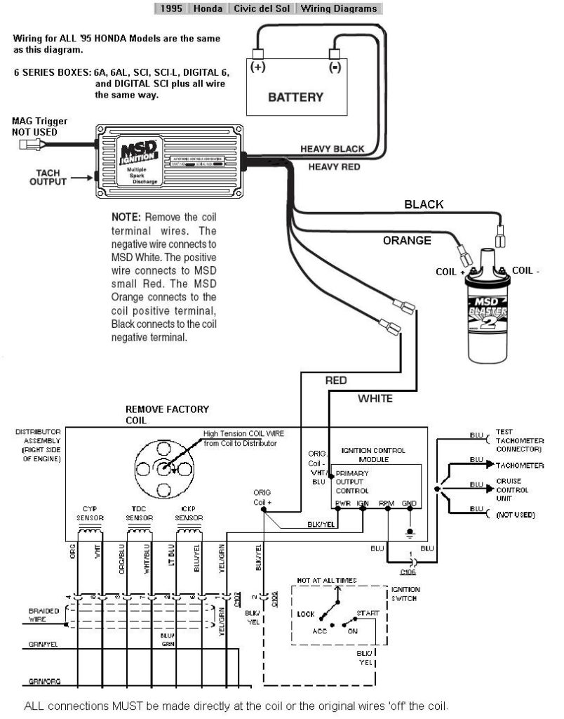
Understanding the terms is the first step to knowing what type of ignition coil you have. The fundamental diagram of ignition wiring illustrates a variety of connections and terminals. There are two primary and secondary connections. Each coil has a specific operating voltage. To determine what kind of coil you own first, you need to determine the voltage at the S1 primary terminal. S1 must also go through resistance testing to determine whether it are a Type A or B coil.
The coil’s low-tension component is to be connected to the chassis positively. This is what is known as the ground for the ignition wiring. The high-tension component supplies the spark plugs with positive. The body of the coil has to connect to the chassis to suppress the effect, but it is not electrically essential. The wiring diagram for the ignition will explain how to connect the terminals of the negative or positive coils. In certain instances it is recommended to conduct a scan at the local auto parts store can help you identify malfunctioning ignition coils.
The black-and-white-striped wire from the harness goes to the negative terminal. Positive terminal receives a white wire that includes a black trace. The black wire connects with the contact breaker. It is possible to check the connections using a paperclip to pull the wires out of the housing. Be sure that you don’t bend the connectors.
Accessory terminals
Ignition wiring diagrams show the various wires used to power the car’s various components. There are generally four color-coded terminals that correspond to the respective component. To identify accessories, red is the starter solenoid’s color, blue for battery and blue for accessories. The “IGN” terminal is used to turn on the car and operate the wipers, as well as other operating features. The diagram shows the connection of the ACCas well as ST terminals.
The terminal referred to as BAT is the place where the battery is. The battery is essential for the electrical system to begin. Furthermore the switch isn’t turned on. The wiring diagram will show the location of the battery of your car. The accessory terminals in your vehicle are connected to the battery and ignition button. The BAT terminal is connected to the battery.
Certain ignition switches have an additional position. This lets users access their outputs from a different place without the ignition. Customers sometimes want the auxiliary output to be used independently from the ignition. For the auxiliary output to be used, plug in the connector with the same color as the ignition. Then connect it with the ACC end of the switch. This is an excellent feature, but there is an important distinction. A lot of ignition switches can be programmed to have an ACC location when the car is in the ACC position. They will also be in the START position once the vehicle is entered the IGN position.
Gallery of 95 Honda Civic Ignition Switch Wiring Diagram
Gallery of 95 Honda Civic Ignition Switch Wiring Diagram


