99 Dodge Ram Ignition Wiring Diagram – First, we will look at the different types of terminals that are found in the ignition switch. These include terminals for Coil, Ignition Switch, and Accessory. Once we know what these terminals are, we will determine the various components in the ignition wiring. Then, we will discuss the functions and the Coil. Next, we’ll discuss the functions of the ignition switch and Coil.
Terminals for ignition switch
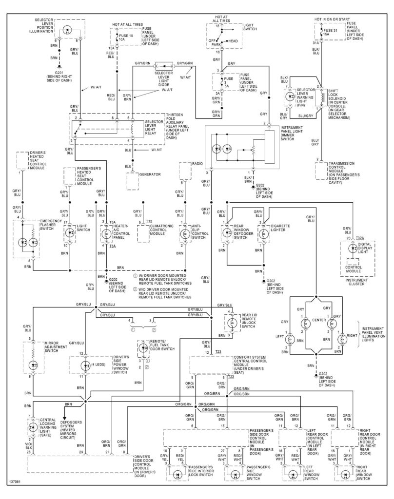
Three switches are located on the ignition switch. Each of these three switches transmits the battery’s current to several different places. The ON/OFF setting of the ignition switch is controlled by the second switch, which supplies the choke with power when it is pushed. Different manufacturers have distinct color-coding systems that correspond to the conductors. OMC utilizes this method. An adapter is included on the ignition switch to allow for the addition of the Tachometer.
While most ignition switch terminals are not original, the numbering for each might not be consistent with the diagram. Verify the electrical continuity first to make sure they’re properly connected to the ignition switch. A simple multimeter will assist you in this. When you’re satisfied that the wires are in good order and you are able to connect the new connector. If your car is equipped with an original ignition switch supplied by the factory (or wiring loom), the wiring loom may differ from that of the car.
To connect the ACC outputs to the auxiliary outputs on your car, you need first know the way these two connections function. The ACC, IGN and START terminals are the primary connections to the ignition switch. They also serve as the primary connections to your radio and stereo. The ignition switch regulates the engine in your car. On older cars, the ignition switch terminals are identified with the alphabets “ACC” as well as “ST” (for the individual magnetic wires).
Terminals for Coil
Understanding the terminology that is used is the initial step towards determining the kind of ignition coil you need. In a basic ignition wiring diagram there are several different connections and terminals, such as two primary and two secondary. The operating voltage of each coil differs. This is why it is crucial to test the voltage at S1 (primary terminal). To determine if the coil is a Type A, C or B coil, you should also check the resistance of S1.
The lower-tension side of the coil must be connected to the chassis’ negative. It is also the ground for an ignition wiring diagram. The high-tension side delivers positively directly to the spark plugs. It is required for suppression purposes that the metallic body of the coil is connected to its chassis, however, it is not necessary. There are also connections of the negative and positive coil’s terminals on an ignition wiring diagram. In some cases it is recommended to conduct a scan at the local auto parts store will be able to diagnose the malfunctioning ignition coils.
The black-and-white-striped wire from the harness goes to the negative terminal. The positive terminal receives the white wire and the trace in black. The contact breaker is linked to the black wire. To test the wires’ connections, employ a paperclip to remove them out of the housing. Be sure that you don’t bend the connectors.
Accessory Terminals
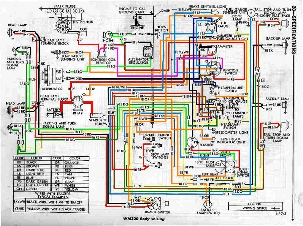
The wiring diagrams for the ignition show the various wires that provide power to the various parts of the vehicle. There are generally four color-coded terminus for each component. The red color is for accessories, yellow to the battery and green is the starter solenoid. The “IGN” terminal can be used to start the car , and also to operate the wipers, as well as other operating functions. This diagram shows how to connect ACC and ST terminals to the rest of components.
The terminal BAT connects the battery to the charger. The electrical system will not start without the battery. The switch also won’t start without the battery. You can view the wiring diagram of your car to see where the batteries of your car are located. The accessory terminals of your car connect to the ignition switch and the battery. The BAT Terminal is connected to the battery.
Some ignition switches come with an additional position. This allows users to access their outputs from another location without the ignition. Sometimes, customers wish to make use of the auxiliary output separately from the ignition. The auxiliary output can be connected by wiring the connector with the same color as your ignition, and then connecting it to the ACC terminal of the switch. Although this is a great feature, there’s one thing to be aware of. Most ignition switches will be in an ACC position if the car is in the ACC, but they’ll be at the START position if the vehicle is in IGN.
Gallery of 99 Dodge Ram Ignition Wiring Diagram
Gallery of 99 Dodge Ram Ignition Wiring Diagram


