Ignition Wire Toyota Ignition Switch Wiring Diagram – The first step is to take a look at the different kinds of terminals on the ignition switch. These include terminals that are used for Coil, Ignition Switch, and Accessory. Once we know the terminals that are utilized, we can begin to determine the various components of the Ignition Wire Toyota Ignition Switch Wiring Diagram. We will also cover the functions of both the Ignition Switch and Coil. The next step is to focus on the accessory terminals.
Terminals for ignition switches
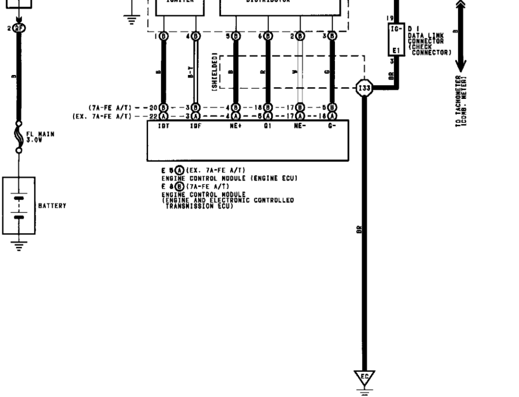
An ignition switch is composed of three different switches. They are responsible for feeding the battery’s power to several locations. The first switch powers the choke. The third switch regulates the ON/OFF function of the ignition switch. Each manufacturer has its individual color-coding system that we’ll discuss in a subsequent article. OMC follows this method. There is a connector in the ignition switch to allow connecting a to a tachometer.
While many ignition switch terminals could not be original, the numbers of each one might not be in line with the diagram. Before plugging in the ignition switch, ensure that you check the continuity. You can do this with an inexpensive multimeter. When you’re satisfied that all wires are in good order, you can attach the new connector. The wiring loom used for the ignition switch supplied by the factory will be different from the one in your vehicle.
It is important to know the differences between the ACC and auxiliary outputs. The ACC, IGN and START terminals are your default connections to the ignition switch. They also serve as the main connections to the radio and stereo. The ignition switch is responsible to turn the engine of your car on and off. Older cars are equipped with ignition switch’s terminals that are labeled “ACC” or “ST” (for individual magnetowires).
Terminals for Coil
The first step to determine the type of ignition coil is to understand the terminology used. In a basic ignition wiring diagram there are a number of different connections and terminals, which include two primary and two secondary. You must determine the type of coil you own by examining the voltage at the primary terminal S1. S1 must also be inspected for resistance to determine if the coil is a Type B, B, or A coil.
The chassis’ negative must be connected to connect the coil’s low-tension side. This is what’s called the ground in the wiring diagram for ignition. The high-tension supply provides the spark plugs with positive electricity directly. It is required for suppression purposes that the metallic body of the coil is connected to the chassis, however it isn’t essential. A wiring diagram can illustrate the connection between the positive and negative coil terminals. There could be an issue with your ignition coil that can be easily diagnosed by scanning it at the auto parts shop.
The black-and-white-striped wire from the harness goes to the negative terminal. The positive terminal is connected to the white wire, which has the black trace. The black wire connects to the contactbreaker. It is possible to remove the black wire from the plug housing with a paper clip If you’re unsure of the connection. Check that you don’t bend the connectors.
Accessory terminals
The wiring diagrams for the ignition show the different wires that power the various components of the car. Typically there are four colored terminals for each part. Red is used to indicate accessories, yellow to the battery and green is the starter solenoid. The “IGN terminal” is used to power the wipers along with other operational features. The diagram illustrates how to connect ACC or ST terminals, and other.
The terminal BAT is the connection for the battery. The electrical system can’t start without the battery. The switch also won’t turn on without the battery. It is possible to look up your wiring diagram to determine where your car’s batteries are located. The ignition switch is connected to the car’s battery. The BAT terminal is connected to the battery.
Certain ignition switches have an accessory setting where users can alter their outputs and control them without having to turn on the ignition. Sometimes, users want to make use of an additional output independent of the ignition. Make use of the additional output by connecting the connector to the ACC terminal on the switch using the same colors. Although this is a great option, there’s a thing you need to know. A majority of ignition switches feature the ACC position when your car is in ACC mode, and a START position when the switch is in IGN.
Gallery of Ignition Wire Toyota Ignition Switch Wiring Diagram

Gallery of Ignition Wire Toyota Ignition Switch Wiring Diagram


