1966 Mustang Ignition Wiring Diagram – In the beginning, we’ll take a look at the various kinds of terminals that are found in the ignition switch. These are the terminals that connect the Ignition, Coil, or Accessory. After we’ve established the purpose of these terminals are used for, we will proceed to discover the various components of the 1966 Mustang Ignition Wiring Diagram. We’ll also be discussing the function of the Ignition switch, as well as the Coil. We will then focus on the accessories terminals.
Terminals for the ignition switch
An ignition switch contains three separate switches that feed the battery’s current to various locations. The ON/OFF setting of the switch that controls the ignition is managed by the first switch, which provides power to the choke when it is pushed. Different manufacturers have different colors-coding systems to match the conductors. OMC uses this method. There is a connector in the ignition switch for attaching the Tachometer.
While the majority of the ignition switch terminals may not be original, the numbering for each one may not be in line with the diagram. Check the continuity of all the wires to ensure they are correctly connected to the ignition switches. A multimeter that is inexpensive can help you do this. Once you’re satisfied with the quality of the connection, you can place the new connector. The wiring loom used in an ignition system switch that is supplied by the manufacturer is distinct.
You must first understand the ways in which the ACC outputs and the auxiliary outputs function in order to join them. The ACC and IGN terminals are the default connections on your ignition switch. the START and IGN terminals are the primary connections for radio and stereo. The ignition switch is responsible for turning the car’s engine to and off. On older cars the ignition switch’s terminals are marked with the initials “ACC”, and “ST” (for distinct magnet wires).
Terminals for coil
Understanding the terminology is the first step to determining which type of ignition coil you’ve got. There are a variety of connections and terminals in a basic ignition wiring schematic, including two primary, and two secondary. Each coil has a specific operating voltage. To determine which type of coil you’ve got the first step is to test the voltage at S1, the primary terminal. S1 should also undergo resistance testing to determine if it are an A or B coil.
The coil with low tension must be connected to the chassis’ minus. It is also the ground for an ignition wiring diagram. The high-tension supply provides positively directly to spark plugs. The metal body of the coil needs to be connected to the chassis for suppression purposes but is not electrically required. The wiring diagram for ignition will also outline the connections of the positive coil terminals. In certain cases it is recommended to conduct a scan at the local auto parts store will help identify malfunctioning ignition coils.
The black-and-white-striped wire from the harness goes to the negative terminal. The other white wire has a black trace on it and it connects to the positive terminal. The black wire connects to the contact breaker. If you’re not sure about the connection between both, you can use a paper clip to remove them from the housing of the plug. Make sure that the terminals aren’t bent.
Accessory terminals
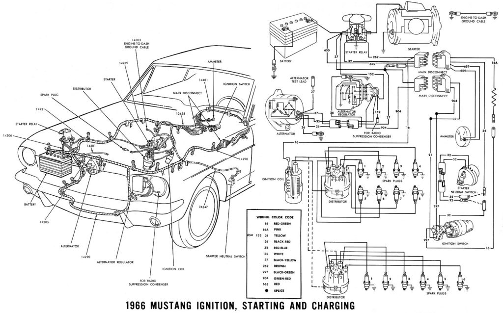
Diagrams of ignition wiring show the different wires that are utilized to power the vehicle’s various components. There are typically four terminals with color codes that are connected to the component. Red refers to accessories, yellow is the battery and green the starter solenoid. The “IGN” terminal can be used to start the car, operate the wipers and other features. The diagram shows how to connect ACC or ST terminals as well as the rest.
The terminal BAT holds the battery. The electrical system can’t be started without the battery. A dead battery can cause the switch to not come on. You may refer to the wiring diagram if you are not sure where the batteries of your car are. Your car’s accessory terminals connect to the ignition switch, as well as the battery. The BAT terminal is connected to the battery.
Certain ignition switches have an accessory position where users can modify their outputs as well as control them without the need to use the ignition. Sometimes, customers want to make use of the auxiliary output separate from the ignition. To use the additional output, wire the connector using identical colors to the ignition, connecting it to the ACC terminal on the switch. While this is a convenient feature, there’s one significant difference. Most ignition switches come with an ACC position when the car is in ACC mode and a START mode when the switch is in IGN.
Gallery of 1966 Mustang Ignition Wiring Diagram
Gallery of 1966 Mustang Ignition Wiring Diagram


