66 Mustang Ignition Switch Wiring Diagram – In the beginning, we’ll look at the different types of terminals in the ignition switch. These are the terminals for the Ignition, Coil, or Accessory. After we’ve identified the purpose of these terminals, it is possible to recognize the various parts of the ignition wiring. Then, we will discuss the functions and the Coil. After that we will move on to the Accessory Terminals.
Terminals for the ignition switch
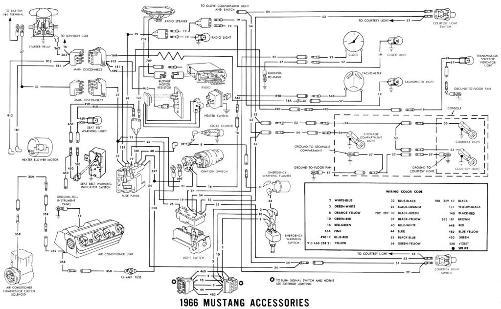
An ignition switch is composed of three switches. They are the ones that supply the battery’s power to various places. The first one supplies power to the choke when it is pushed. The second is the switch that controls the ignition’s ON/OFF positions. Different manufacturers use different color-coding methods to identify different conductors. We’ll discuss this in a separate article. OMC utilizes this method. This connector allows the attachment of a speedometer to the ignition switch.
While the majority of ignition switch terminals don’t carry an original number, they may have a different number. To make sure that your wires are correctly connected to the switch you should check their continuity. You can check this using a simple multimeter. Once you are satisfied with the continuity of the wires, it is time to install the new connector. If you are using an ignition switch that is supplied by the manufacturer the wiring loom may be distinct from the one that is in your car.
Before you can connect the ACC outputs to your car’s auxiliary outputs it is crucial to be familiar with the fundamentals of these connections. The ACC and IGN connectors are the standard connections for your ignition switch. Although the START, IGN, and ACC terminals are the main connections for radios or stereo, the START/IGN terminals are the most important ones. The ignition switch switches the engine of your car ON and off. On older cars, the ignition switch terminals are marked with the letters “ACC”, and “ST” (for distinct magnetic wires).
Terminals for Coil
To determine the type of ignition coil, the initial step is to understand the terms. In a basic diagram of the wiring for ignition you’ll see several different connections and terminals, such as two primary and two secondary. Each coil operates at a specific voltage. The first step to determine which type you have is to check the voltage of S1 or the primary terminal. Also, you should check S1 for resistance in order to determine if it’s a Type A, B, or C coil.
The coil’s low-tension side must be connected to the chassis’ positive. This is the wiring diagram you will find in the diagram of wiring. The high-tension component supplies the spark plugs with positive. To prevent noise the body of the coil must be connected to the chassis. It is not necessary to connect the coil electrically. The wiring diagram for the ignition will demonstrate how to connect the terminals of either the negative or positive coils. There could be an issue with your ignition coil which can be identified by scanning it in an auto parts store.
The black-and-white-striped wire from the harness goes to the negative terminal. Positive terminal receives a second white wire, which has a black trace. The contact breaker is linked to the black wire. You can take the black wire from the housing of the plug with a paper clip in case you are uncertain about the connection. Make sure that the terminals aren’t bent.
Accessory terminals
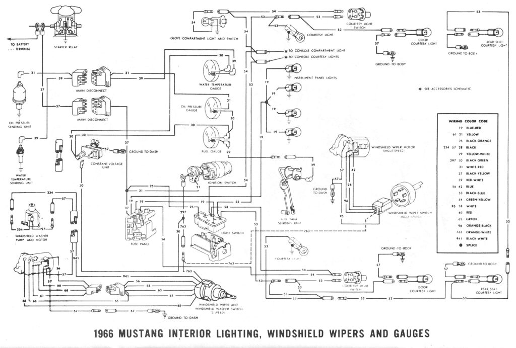
Diagrams of ignition wiring show the wires that are used in the vehicle’s power supply. In general there are four distinct color-coded terminals for each component. To identify accessories, red stands the starter solenoid’s color, blue for battery, and blue for accessory. The “IGN” terminal is used to start the car, control the wipers, and other functions. The diagram below shows how to connect both the ACC terminal as well as the ST terminals to various components.
The battery is connected to the terminal whose name is BAT. Without the battery the electrical system will not start. Furthermore, the switch won’t begin to turn on. To locate your car’s battery look over your wiring diagram. The accessory terminals of your car are connected to the ignition switch, as well as the battery. The BAT terminal is connected to the battery.
Some ignition switches feature the “accessory” position that allows users to control their outputs without having to use the ignition. Some customers want an auxiliary output that can be used separately from the ignition. You can use the additional input by connecting the connector to the ACC terminal. This option is useful however it does have one key differentiator. The majority of ignition switches have an ACC position when the vehicle is in ACC however they will be at the START position when the vehicle is in IGN.
Gallery of 66 Mustang Ignition Switch Wiring Diagram
Gallery of 66 Mustang Ignition Switch Wiring Diagram


