Chinese Atv Ignition Switch Wiring Diagram – First, we will take a look at the various kinds of terminals found in the ignition switch. These are terminals for Coil, Ignition Switch, and Accessory. Once we know what these terminals do, we will determine the various components in the ignition wiring. We’ll also discuss the roles of both the Ignition Switch and the Coil. After that, we will focus on the accessories terminals.
Terminals for ignition switch
An ignition switch is comprised of three switches. They supply the battery’s voltage to different places. The first switch is the one that supplies power to the choke and the third switch toggles the ON/OFF state of the switch. Different manufacturers have different color-coding systems that correspond to the conductors. OMC follows this scheme. The connector permits the connection of a speedometer to the ignition switch.
Although most ignition switch terminals can be duplicated, the numbers may not match the diagram. Check the continuity of the wires to determine if they’re plugged into the ignition switch correctly. This can be checked with a multimeter that is inexpensive. Once you are satisfied that the wires are in good order, you can attach the new connector. The wiring loom in a factory-supplied ignition system switch differs.
The first step is to understand the distinctions between ACC and secondary outputs. The ACC terminals and IGN terminals are the primary connections to the ignition switch. The START and IGN connections are the most important connections for radio and stereo. The ignition switch is responsible for turning the engine of your car to and off. The terminals of older cars’ ignition switches are labeled with “ACC” and ST (for individual magneto wires).
Terminals for coil
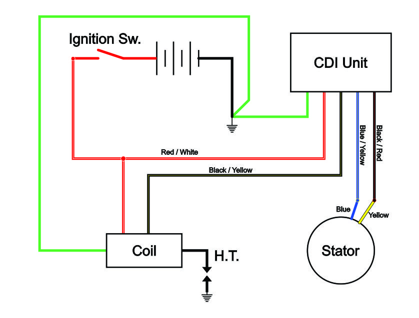
Understanding the terminology that is used is the initial step towards finding out the right kind of ignition coil you need. The diagram of the basic ignition wiring depicts various connections and terminals. There are two primary and secondary connections. The coils are equipped with a particular operating voltage. The initial step to determine which one you’re using is to test the voltage on S1, the primary terminal. S1 must be checked for resistance to determine if the coil is type A, B and/or C.
The negative of the chassis must be connected to the side of low-tension. This is the ground of the ignition wiring. The high-tension component supplies the spark plugs with positive. For suppression purposes the body of the coil must be connected to chassis. However, it is not necessary to connect the coil electrically. It is also possible to see the connections between the negative and positive coil’s terminals on the diagram of the ignition wiring. Sometimes, a visit to an auto parts shop can detect a defective ignition wire.
The black-and-white-striped wire from the harness goes to the negative terminal. The positive terminal is connected to the white wire with a trace in black. The black wire connects to the contact breaker. It is possible to check the connections with a paperclip to remove the wires of the housing. Be sure to check that the terminals haven’t been bent.
Accessory terminals
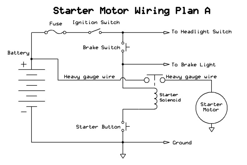
The wiring diagrams of the ignition illustrate the different wires used to provide power to the various parts of the car. In general there are four distinct color-coded terminals for each component. The accessories are colored red and the battery yellow the starter solenoid green. The “IGN terminal” is used to power the wipers and other operating features. The diagram shows how you can connect the ACC and ST terminals to the rest of the components.
The terminal BAT is the connector for the battery. The electrical system will not start without the battery. The switch will not turn on if the battery isn’t present. To find your car’s battery, check your wiring diagram. The accessory terminals in your car are connected with the battery and the ignition button. The BAT Terminal is connected to the battery.
Some ignition switches come with an additional position. This lets users access their outputs from another location without having to turn on the ignition. Some customers want an auxiliary output that can be operated independently of the ignition. It is possible to use the secondary input by connecting it to the ACC terminal. This is a great option, but there’s one important difference. Most ignition switches are configured to have an ACC position when the vehicle is in the ACC position, whereas they’re set to the START position when the vehicle is in the IGN position.
Gallery of Chinese Atv Ignition Switch Wiring Diagram

Gallery of Chinese Atv Ignition Switch Wiring Diagram


