07 Optima Key Ignition Wiring Schematic Diagram – First, we will look at the various types of terminals that are used on the ignition switch. These are the terminals used for Coil, Ignition Switch, and Accessory. Once we have identified what these terminals are, we will determine the various components in the ignition wiring. In addition, we will discuss the functions of both the Ignition Switch and the Coil. Following that, we’ll shift our attention to Accessory terminals.
Terminals for ignition switch
The ignition switch has three switches. They transmit the battery’s voltage to different locations. The ON/OFF setting of the switch that controls the ignition is managed by the first switch, which delivers power to the choke whenever it’s pushed. Different manufacturers have distinct color-coding systems that correspond to the conductors. OMC uses this method. The ignition switch comes with a connector for adding the Tachometer.
While most ignition switch terminals are duplicated, the numbers might not be in line with the diagram. Verify the integrity of the wires first to ensure they are correctly plugged in the ignition switch. This can be accomplished using a cheap multimeter. Once you’ve verified the integrity of the wires you can connect the connector. The wiring loom of an ignition switch that’s supplied by the manufacturer will differ from the one that you have in your car.
It is important to know the differences between ACC and auxiliary outputs. The ACC terminals and IGN terminals function as the primary connections to the ignition switch. The START and IGN connections are the most important connections for radio and stereo. The ignition switch turns the car’s engine on and OFF. The terminals for the ignition switch on older vehicles are marked with the initials “ACC” as well as “ST” (for individual magneto wires).
Terminals for coil
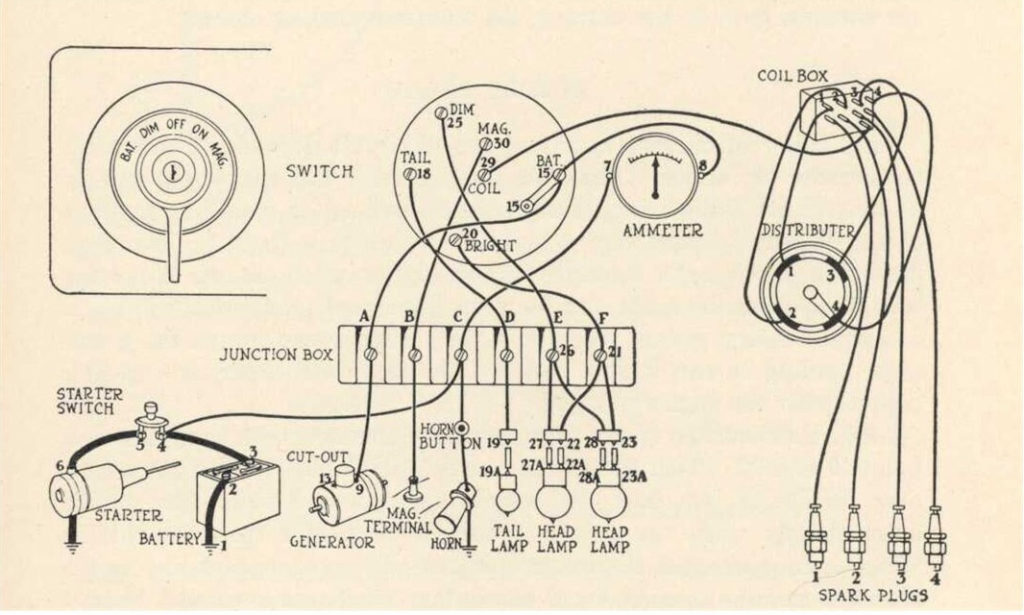
The first step in determining the type of ignition coil is to understand the terms employed. The basic ignition wiring diagram shows a number different connections and terminals. There are two primary and one secondary. Each coil is operating at a certain voltage. The first step to determine the kind you’re using is to examine the voltage on S1, or the primary terminal. It is also recommended to test S1 for resistance to determine if it’s an A, B, or C coil.
The coil’s low-tension side must be connected with the chassis positive. This is also the ground in the wiring diagram for ignition. The high tension part supplies positive directly the spark plugs. For suppression purposes the body of the coil must be connected to the chassis. But, it’s not necessary to electrically connect. The diagram of the ignition wiring will also outline the connections of the positive coil terminals. Sometimes, a visit to an auto parts store could identify a problem with the ignition wire.
The black-and-white-striped wire from the harness goes to the negative terminal. The terminal that is negative is served by the black trace that’s attached to the white wire. The black wire connects to the contact breaker. To check the connections, employ a paperclip, or a pencil to lift them out from the plug housing. Also, see that the terminals aren’t bent.
Accessory terminals
The ignition wiring diagrams illustrate the various wires utilized to power the vehicle’s various parts. Each component has four distinct connections that are color coded. Red is used for accessories and yellow is for the battery, and green is the solenoid for starters. The “IGN terminal” is used to provide power to the wipers and other operating functions. This diagram shows how you can connect ACC and ST terminals to the rest of components.
The terminal BAT is where the battery is. The electrical system is not able to start without the battery. A dead battery can make the switch not come on. You can refer to your wiring diagram if you’re not sure where the batteries of your car are located. The ignition switch and the battery are connected via accessory terminals. The BAT connector is connected to your battery.
Certain ignition switches have a separate “accessory” position, in which users can control their outputs without using the ignition. Sometimes, a customer wants to make use of the auxiliary output separately from the ignition. It is possible to use the additional input by connecting it to the ACC terminal. Although this is a useful option, there’s an important difference. Most ignition switches are configured to have an ACC position when the vehicle is in the ACC position, while they’re in the START position when the car is in the IGN position.
Gallery of 07 Optima Key Ignition Wiring Schematic Diagram
Gallery of 07 Optima Key Ignition Wiring Schematic Diagram


