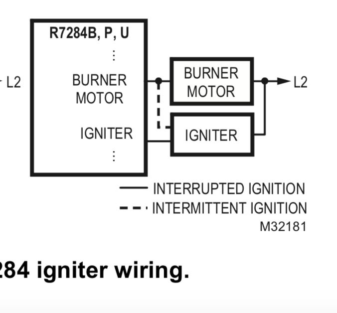
Allanson Ignition Transformer Wiring Diagram – The first step is to take a look at the different kinds of terminals for the ignition switch. These are the terminals that connect the Ignition, Coil, or Accessory. Once we’ve established the purpose of the terminals we can recognize the various parts of the ignition wiring. We’ll also go over the roles of the Ignition switch and Coil. After that, we’ll turn our attention to Accessory terminals.
Ignition switch terminals
An ignition switch contains three different switches that direct the battery’s current to various destinations. The first is used to turn on the choke by pushing it. Then, the second is for the ON/OFF setting. Different manufacturers have distinct colour-coding systems that correspond to the conductors. OMC utilizes the same system. The connector allows for the connection of a speedometer to the ignition switch.
While the majority of ignition switch terminals don’t carry an original number, they may be equipped with a different number. To make sure that your wires are correctly plugged in to the ignition switch you should check their continuity. This can be done with a cheap multimeter. When you are happy with the continuity of the wires you can connect the new connector. The wiring loom used in an ignition system switch that is supplied by the manufacturer differs.
For connecting the ACC outputs to the auxiliary outputs on your vehicle, you have first know how these two connections work. The ACC, IGN and START terminals are your default connection to the ignition switch. They also serve as the primary connections to the radio and stereo. The ignition switch controls the car’s engine. Older cars are identified with the alphabets “ACC”, “ST”, (for individual magneto cables) at the ignition switch terminals.
Terminals for coil
The language used to decide the type and model of the ignition coil is the most important thing. A basic ignition wiring layout will show you a number of terminals and connections. Each coil comes with its own operating voltage. To determine which type of coil you have the first step is to determine the voltage at S1, the primary terminal. S1 should also be tested for resistance to determine if it’s an A, Type B or an A coil.
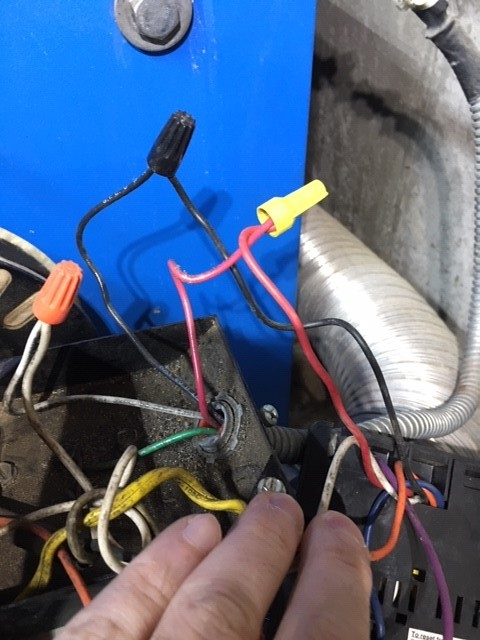
The coil’s low-tension side must be connected to the chassis positive. This is what is known as the ground for the wiring for ignition. The high-tension supply delivers positive directly to spark plugs. To reduce the noise the body of the coil must be connected to the chassis. However, it is not necessary to electrically connect. The diagram of the ignition wiring will also indicate how to connect the positive coil’s terminals. In certain instances, you’ll find that the ignition coil is damaged and is easily identified with scanning in an auto parts store.
The black-and-white-striped wire from the harness goes to the negative terminal. Positive terminal gets the second white wire, which includes a black trace. The black wire is connected to the contact breaker. You can examine the connections using a paperclip to take the wires out from the housing. Check that the terminals aren’t bent.
Accessory terminals
Diagrams of ignition wiring illustrate the wiring used to power various parts of the vehicle. There are typically four different color-coded terminus for each component. For accessories, red stands the starter solenoid’s color, blue for battery and blue for accessories. The “IGN” terminal is used to start the car , and also to operate the wipers and other operating features. The diagram shows how to connect the ACC and ST terminals to the rest of the components.
The terminal BAT connects the battery to the charger. The electrical system is not able to begin without the battery. The switch will not turn on if the battery isn’t there. To find the battery in your car look over your wiring diagram. The ignition switch and battery are connected via accessory terminals. The BAT terminal is connected with the battery.
Certain ignition switches have an accessory position. This allows users to access their outputs from a different location without the ignition. Sometimes, a customer wants to use an auxiliary output that is separate from the ignition. In order to use the auxiliary output, connect the connector with the same colors as ignition, and connect it to the ACC terminal on the switch. While this is an excellent feature, there’s one thing you should know. Most ignition switches are configured to be in an ACC position when the car is in the ACC position, but they’re in the START position when the vehicle is in the IGN position.
Gallery of Allanson Ignition Transformer Wiring Diagram
Gallery of Allanson Ignition Transformer Wiring Diagram


