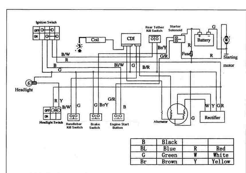
Atv Ignition Coil Wiring Diagram – First, we will look at the various types of terminals for the ignition switch. They include terminals for Coil, Ignition Switch, and Accessory. After we’ve identified the purpose of these terminals, we will be able to recognize the various parts of the ignition wiring. We’ll also discuss the functions of the Ignition switch, as well as the Coil. Following that, we’ll shift our attention to the Accessory terminals.
Terminals for ignition switches
There are three different switches in the ignition switch, and they transmit the battery’s current voltage to several different destinations. The choke is powered by the first switch. The third switch regulates the ON/OFF switch of the ignition switch. Different manufacturers use different color-coding methods for different conductors. We’ll discuss this in a separate article. OMC uses this method. A connector can be added to the ignition switch in order to include the digital tachometer.
Although the majority of ignition switch terminals aren’t original, the numbers for each might not be consistent with the diagram. Before you plug into the ignition switch, be sure to test the continuity. A multimeter is an excellent instrument to verify the continuity. Once you are satisfied with the integrity of the wires, install the new connector. The wiring loom of an ignition switch that is supplied by the factory will be different from the one you have in your car.
You must first understand the ways in which the ACC outputs and the auxiliary outputs function to connect them. The ACC/IGN connections function as the default connections on the ignition switch. The START/IGN connections connect to the radio or stereo. The ignition switch is the one that turns the engine of your car on and off. The terminals on older cars ignition switches are marked with “ACC” as well as ST (for the individual magneto wires).
Terminals for coil
Understanding the terms utilized is the first step to determining what type of ignition coil. A basic diagram of the wiring will reveal a variety of terminals and connections. The voltage that operates on each coil differs. This is why it is crucial to test the voltage at the S1 (primary terminal). To determine whether it’s a Type A, C or B coil it is recommended to also test the resistance on S1’s.
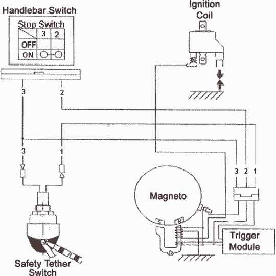
The coil’s low-tension side must be connected with the chassis positively. This is the ground of the ignition wiring. The high tension side provides positive power directly to the spark plugs. The aluminum body of the coil needs to be linked to the chassis to prevent it from being smothered but isn’t required. There are also connections between the positive and the negative coil’s terminals on an diagram of the ignition wiring. You may find an ignition coil problem which can be identified by scanning it in an auto parts retailer.
The black-and-white-striped wire from the harness goes to the negative terminal. The other white wire has a black color and goes to the negative terminal. The black wire connects to the contact breaker. To check the connections between the two wires employ a paperclip to lift them off the housing. Make sure that the terminals do not bend.
Accessory terminals
The ignition wiring diagrams illustrate the various wires utilized to power the vehicle’s various components. There are usually four terminals with color codes that are connected to the component. The red color represents accessories, yellow is for the battery, and green for the solenoid for starters. The “IGN” terminal is used to start the car, operating the wipers and various other functions. This diagram demonstrates how to connect ACC and ST terminals with the other components.
The terminal BAT connects the battery to the charger. The electrical system cannot start without the battery. Also, the switch won’t start without the battery. If you don’t know the location of your car’s battery located, you can review your wiring diagram to figure out how to locate it. The accessory terminals in your car are connected with the battery and ignition button. The BAT terminal is connected to the battery.
Some ignition switches feature an “accessory” setting that allows users to control their outputs , without needing to utilize the ignition. Some customers prefer to make use of an additional output that is independent of the ignition. In order for the auxiliary output be used, wire the connector in the same color as the ignition. Then connect it with the ACC end of the switch. This feature of convenience is fantastic however, there’s one difference. The majority of ignition switches are configured to show an ACC status when the car is in either the ACC or START position.
Gallery of Atv Ignition Coil Wiring Diagram
Gallery of Atv Ignition Coil Wiring Diagram


