Ba Falcon Ignition Switch Wiring Diagram – We will first examine the various types of terminals in the ignition switch. These terminals include the Ignition switch as well as the Coil along with the Accessory. Once we’ve determined the function of the terminals we will be able to identify the various parts of the ignition wiring. We’ll also go over the roles of the Ignition switch, as well as the Coil. After that, we will focus on the accessories terminals.
Terminals for ignition switches
There are three switches on the ignition switch, and they transmit the battery’s current voltage to various locations. The first one is utilized to drive the choke through pushing it, and another switch controls the ON/OFF setting. Different manufacturers have different color-coding schemes to identify different conductors. This will be covered in another article. OMC uses this method. Connectors can be attached to the ignition switch in order to include the digital Tachometer.
Even though some ignition switch terminals do not have the original design however, the numbers may not match the diagram. Verify the electrical continuity first to ensure they are correctly plugged in the ignition switch. You can check this using an inexpensive multimeter. When you’re satisfied that the wires are in good order and you are able to connect the new connector. The wiring loom used for an ignition switch that is supplied by the manufacturer will differ from the one in your car.
In order to connect the ACC outputs to the auxiliary outputs on your car, you need first know the way these two connections function. The ACC and IGN terminals are the default connections for your ignition switch. the START and IGN terminals are the main connections for the radio and stereo. The ignition switch is accountable for turning the car’s engine on and off. Older cars are identified with the alphabets “ACC”, “ST”, (for individual magneto cables) at the ignition switch’s terminals.
Terminals for coil
To determine the type of ignition coil, the initial step is to know the terms. The diagram of the basic ignition wiring shows a number different connections and terminals. There are two primary and secondary connections. The operating voltage of every coil is different. Therefore, it is essential to first check the voltage at S1 (primary terminal). S1 should also undergo resistance testing to determine if it is an A or B coil.
The low-tension end of the coil must be connected to the chassis”negative. This is what you see in the diagram of wiring. The high-tension component provides the spark plugs with positive. It is essential for the purpose of suppression that the body of the coil’s metal be connected to the chassis, however it isn’t essential. You will also see the connections between the positive and the negative coil’s terminals on an diagram of the ignition wiring. It is possible to find an ignition coil problem that is easily identified by looking it up at an auto parts store.
The black-and-white-striped wire from the harness goes to the negative terminal. The positive terminal also receives the white wire that includes a black trace. The contact breaker is connected to the black wire. To verify the connections, make use of a paperclip or pencil to lift them out of the plug housing. Be sure the terminals don’t bend.
Accessory terminals
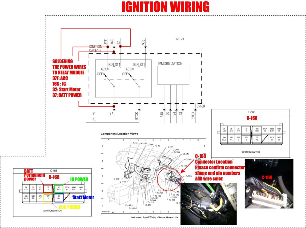
The wiring diagrams of the ignition illustrate the various wires that power the various components of the vehicle. There are generally four colored terminus lines for each component. The accessories are colored red, the battery is yellow and the starter solenoid is green. The “IGN” terminal is used to turn on the vehicle and control the wipers and other operating functions. The diagram shows the connection between the ACCand ST terminals.
The terminal known as BAT is where the battery is connected. The electrical system will not start in the event that the battery isn’t connected. Furthermore the switch isn’t turned on. You may refer to the wiring diagram if you are not sure where the batteries of your car are located. The ignition switch is connected to the car’s battery. The BAT terminal is connected with the battery.
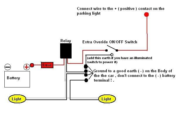
Certain ignition switches provide the option of an “accessory position” that lets users adjust their outputs independently of the ignition. Users may wish to utilize the auxiliary output separately from the ignition. To make use of the auxiliary output, wire the connector with the same colors as ignition, and connect it to the ACC terminal on the switch. This feature is convenient however, it does have one major differentiator. Most ignition switches are set to operate in the ACC position when the car is in the ACC position, whereas they’re set to the START position when the vehicle is in the IGN position.
Gallery of Ba Falcon Ignition Switch Wiring Diagram
Gallery of Ba Falcon Ignition Switch Wiring Diagram


