Bad Boy Mower Ignition Switch Wiring Diagram – Let’s first take a look at the different types of terminals used on the ignition switch. These are the terminals that connect the Ignition, Coil, or Accessory. Once we understand the function of each kind of terminal, it is possible to determine the components of the ignition wiring. We’ll also discuss the functions as well as the Coil. After that we will discuss the Accessory Terminals.
Terminals for ignition switches
There are three different switches in an ignition switch that feed the battery’s voltage to a variety of destinations. The first switch is the one that supplies power to the choke while the second switch controls the ON/OFF status of the ignition switch. Different manufacturers have their own color-coding system for the different conductors, which is documented in another article. OMC utilizes this method. A connector can be added to the ignition switch to add a digital Tachometer.
While the majority of ignition switch terminals don’t have an initial number, they could have a different number. Check the continuity of the wires first to make sure they’re connected correctly to the ignition switch. A multimeter that is inexpensive can assist you in this. After you’re sure that all wires are running in good harmony and you are able to connect the new connector. The wiring loom for an ignition switch that is supplied by the factory will be different from the one you have in your car.
In order to connect the ACC outputs to the auxiliary outputs on your vehicle, you have to understand the way these two connections function. The ACC and IGN terminals are the default connections on your ignition switch, and the START and IGN terminals are the primary connections for the stereo and radio. The ignition switch operates the engine’s switch to turn off or on. The terminals on older cars’ ignition switches are labeled by “ACC” as well as ST (for the individual magneto wires).
Terminals for coil
The terminology used to determine the kind and model of the ignition coil is the most important thing. A basic diagram of the wiring will provide you with a range of connections and terminals. The coils have a specific operating voltage. The first step in determining which type you have will involve testing the voltage of S1 the primary terminal. S1 should also undergo resistance testing to determine if it’s a Type A or B coil.
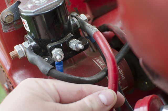
The lower-tension side of the coil should be connected to the chassis the negative. This is what’s called the ground in the ignition wiring diagram. The high-tension side supplies positively direct to the spark plugs. To reduce the noise, the coil’s metal body must be connected to the chassis. But, it’s not necessary to connect the coil electrically. The wiring diagram for the ignition will explain how to connect the terminals of either the negative or positive coils. Sometimes, a check at an auto parts store could identify a problem with the ignition wire.
The black-and-white-striped wire from the harness goes to the negative terminal. The positive terminal is connected to the white wire, which has an trace in black. The black wire connects to the contactbreaker. It is possible to check the connections using a paperclip to remove the wires of the housing. Be sure to check that the terminals aren’t bent.
Accessory terminals
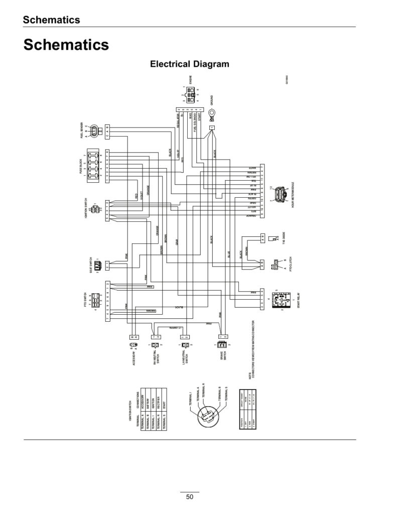
Diagrams of ignition wiring show the different wires that are used to power the car’s various parts. In general, there are four different colors-coded terminals that are used for each component. Red is for accessories, yellow is for the battery, while green is the solenoid for starters. The “IGN” terminal allows you to start the car, manage the wipers or other features that operate. The diagram below shows how to connect both the ACC terminal and ST terminals to other components.
The terminal BAT is the connection to the battery. Without the battery, the electrical system does not start. Additionally, the switch doesn’t turn on. A wiring diagram can tell you the location of the battery of your car. Your car’s accessory terminals connect to the ignition switch as well as the battery. The BAT connector is connected to your battery.
Some ignition switches include an accessory position where users can alter their outputs and manage them without having to turn on the ignition. Some customers may prefer to use the auxiliary output separately from the ignition. In order for the auxiliary output be used, wire the connector with the same shade as that of the ignition. Then connect it with the ACC end of the switch. This convenience feature is great however, there’s one distinction. Many ignition switches have an ACC position when your car is in ACC mode and a START position when you are in IGN.
Gallery of Bad Boy Mower Ignition Switch Wiring Diagram
Gallery of Bad Boy Mower Ignition Switch Wiring Diagram


