Basic Ignition Wiring Diagram – Let’s first examine the different kinds and functions of terminals found in the ignition switches. These are the terminals used for Coil, Ignition Switch, and Accessory. After we’ve established what these kinds of terminals are, we will proceed to identify the different parts of the Basic Ignition Wiring Diagram. We’ll also discuss the functions of the Ignition switch, and Coil. The next step is to focus on the accessory terminals.
Terminals for ignition switches
Three switches are found on the ignition switch. Each of these three switches transmits the battery’s current to various locations. The first switch provides power to the choke when it is pushed. The second is the ignition switch’s ON/OFF position. Different manufacturers use different colors for various conductors. This is explained in a separate article. OMC uses this system. The adapter is attached to the ignition switch to allow for the addition of an tachometer.
Although most ignition switch terminals are duplicated, the numbers might not be consistent with the diagram. Before you plug into the ignition switch, make sure to check the continuity. A cheap multimeter can assist you in this. After you’re sure that all wires are in good continuity, you can attach the new connector. If your car has an original ignition switch supplied by the factory (or an electrical loom) The wiring loom will differ from that in your vehicle.
It is important to know the differences between the ACC and auxiliary outputs. The ACC and IGN connectors are the standard connections for your ignition switch. Although the START, IGN, and ACC terminals are primary connections for radios or stereo, the START/IGN terminals are the main ones. The ignition switch controls the car’s engine. The terminals of older cars ignition switches are marked by “ACC” and ST (for specific magneto wires).
Terminals for coil
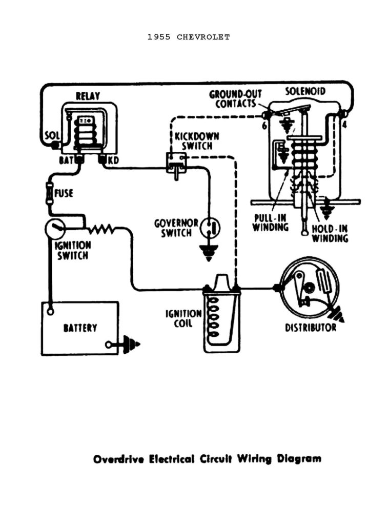
The language used to decide the kind and model of the ignition coil is the first thing. A basic ignition wiring diagram will display a range of terminals and connections, including two primary and two secondaries. Each coil comes with its own operating voltage. To determine the type of coil you have, the first step is to check the voltage at S1, which is the primary terminal. S1 must also be subjected to resistance tests to determine if it’s an A or B coil.
The chassis’ negative must be connected to the low-tension side. This is the ground of the ignition wiring. The high-tension side provides the spark plugs with positive. It is essential for the purpose of suppression that the metallic body of the coil is connected to its chassis, but not essential. There are also connections of the negative and positive coil’s terminals on an diagram of the ignition wiring. Sometimes, a check at an auto parts store could detect a defective ignition wire.
The black-and-white-striped wire from the harness goes to the negative terminal. The white wire is the other one. It is black with a trace, and it goes to the positive terminal. The black wire connects to the contact breaker. If you’re not certain about the connection between both, you can use the clip of a paperclip to remove them from the plug housing. It’s also crucial to ensure that the terminals aren’t bent.
Accessory terminals
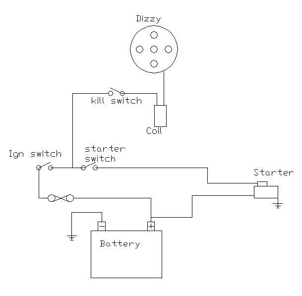
Diagrams of ignition wiring show the various wires used to power the car’s various parts. In general there are four colored terminals for each part. The red color is used for accessories while yellow is the battery, while green is the solenoid for starters. The “IGN” terminal lets you start the car, control the wipers, or any other operation features. The diagram shows the connection of the ACC- and ST terminals.
The terminal known as BAT is the location where the battery is. The electrical system won’t start when the battery isn’t connected. A dead battery can cause the switch to not turn on. To find the battery in your car, check your wiring diagram. The accessory terminals in your vehicle are connected to the battery and the ignition button. The BAT terminal is connected with the battery.
Some ignition switches have the “accessory” position that permits users to control their outputs without having to use the ignition. Sometimes, customers would like the output of the auxiliary to be used separately from the ignition. You can use the auxiliary output by connecting it to an ACC terminal on the switch with the same colors. This is a great convenience feature, but there is one difference. The majority of ignition switches have an ACC position if the car is in ACC however, they’ll be in the START position if the car is in IGN.
Gallery of Basic Ignition Wiring Diagram
Gallery of Basic Ignition Wiring Diagram


