Boyer Bransden Ignition Wiring Diagram – First, we will examine the various types of terminals that are found on the ignition switch. These include the terminals that are for the Ignition switch, Coil, and Accessory. Once we know the purpose of these terminals are for then we can identify the different parts of the Boyer Bransden Ignition Wiring Diagram. In addition, we will discuss the function of the Ignition switch and Coil. After that, we will focus on the accessories terminals.
Ignition switch terminals
Three switches are located in an ignition switch. Each of these three switches transmits the battery’s current to a variety of destinations. The first one is used to drive the choke through pushing it, and another switch controls the ON/OFF position. Different manufacturers have their own color-coding system for the different conductors, that is described in a separate article. OMC utilizes this method. A tachometer adapter is installed on the ignition switch, allowing for the addition of a tachometer.
While most ignition switch terminals are duplicated, the numbers may not match the diagram. The first step is to check the continuity of all wires to ensure that they are properly plugged into the ignition switches. This can be checked using a cheap multimeter. Once you’re satisfied about the integrity of your wires, you’ll be able to connect the new connector. If your car is equipped with an original factory-supplied ignition switch (or an electrical loom), the wiring loom might differ from that in your car.
Before connecting the ACC outputs to your car’s auxiliary outputs, it is important to understand the basics of these connections. The ACC, IGN and START terminals are the default connections to the ignition switch. They also serve as the primary connections to the radio and stereo. The ignition switch is accountable to turn the car’s engines on and off. The terminals of older cars ignition switches are identified with “ACC” as well as ST (for the individual magneto wires).
Terminals for coil
To determine the type of ignition coil, the initial step is to understand the terms. In a basic diagram of the wiring for ignition, you will see a number of different terminals and connections, including two primary and two secondary. The coils have a specific operating voltage. The first step to determine which one you’re using is to test the voltage on S1, the main terminal. S1 must also be inspected for resistance in order to identify if it’s an A, Type B, or A coil.
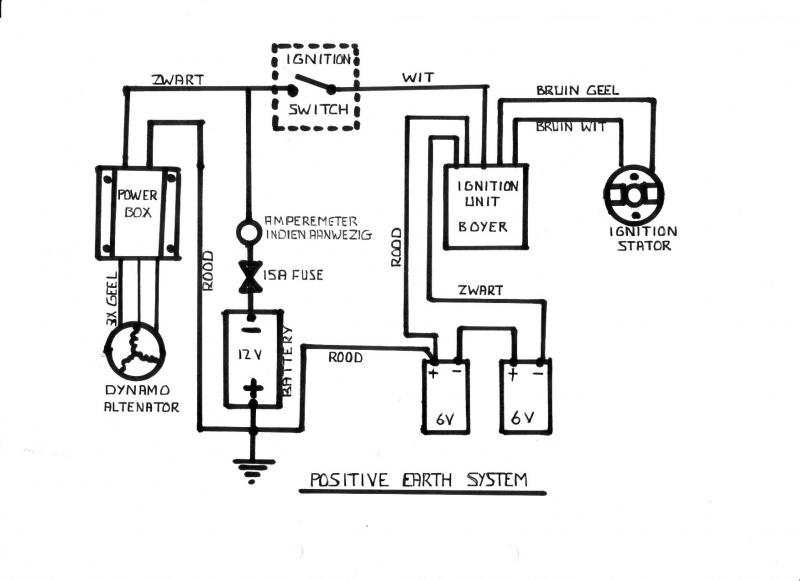
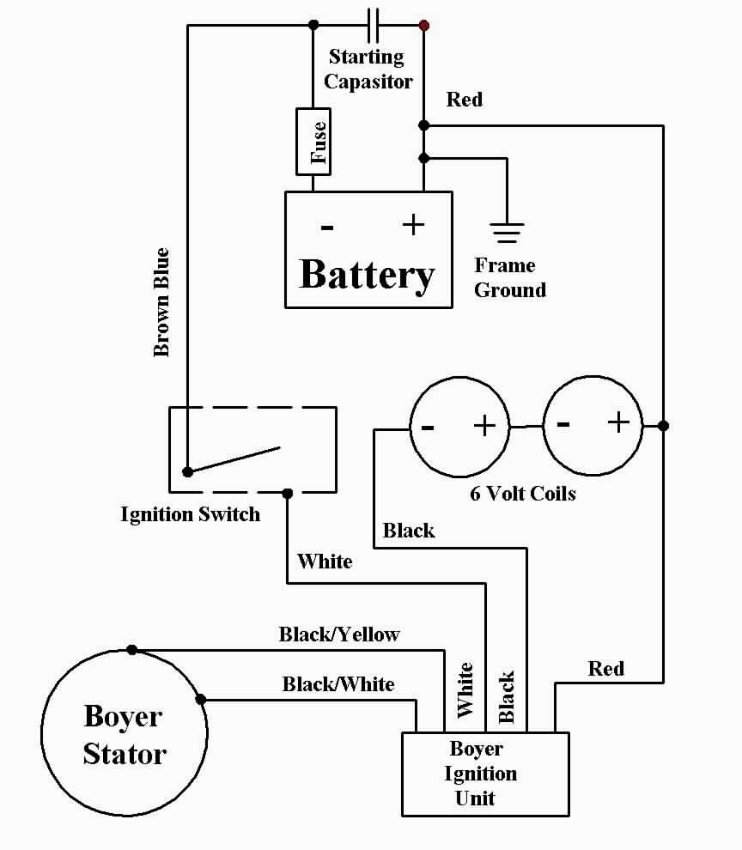
The lower-tension side of the coil needs to be connected to the chassis’ negative. It is also the ground on the diagram of ignition wiring. The high-tension side is a positive connection to the sparkplugs. The metal body of the coil needs to connect to the chassis to suppress the effect but is not electrically necessary. The wiring diagram will also illustrate the connection between the positive and negative coils. In certain cases it is recommended to conduct a scan at the local auto parts store will help identify malfunctioning ignition coils.
The black-and-white-striped wire from the harness goes to the negative terminal. The positive terminal also receives a second white wire, which is black in its trace. The black wire connects with the contact breaker. If you’re not sure about the connections of the two, try using an old paper clip to take them from the plug housing. Be sure the terminals don’t bend.
Accessory terminals
The diagrams for ignition wiring depict the wires used in the power supply of the vehicle. Each component has four distinct color-coded connections. Red is used to indicate accessories, yellow the battery and green the starter solenoid. The “IGN terminal is used to start the car, operating the wipers and other functions. The diagram below illustrates how to connect the ACC terminal and ST terminals to the other components.
The battery is attached to the terminal called BAT. Without the battery, the electrical system does not start. The switch won’t turn on if the battery isn’t present. It is possible to refer to your wiring diagram if unsure where your car’s batteries are located. The ignition switch is connected to the battery of your car. The BAT connector connects to your battery.
Certain ignition switches come with the “accessory” position that permits users to regulate their outputs without needing to utilize the ignition. Sometimes, customers want to use an auxiliary output that is independent of the ignition. In order for the auxiliary output be used, wire the connector with the same color as the ignition. Then , connect it to the ACC end of the switch. Although this is a fantastic feature, there’s something you should know. Some ignition switches are set to have an ACC location when the car has moved into the ACC position. They’ll also be in the START position once the vehicle is moved into the IGN position.
Gallery of Boyer Bransden Ignition Wiring Diagram
Gallery of Boyer Bransden Ignition Wiring Diagram


