Boyer Ignition Wiring Diagram – In the beginning, we’ll look at the different types of terminals that are found in the ignition switch. The terminals are the Ignition switch as well as the Coil along with the Accessory. Once we have established the purpose of these terminals are for then we can identify the different parts of the Boyer Ignition Wiring Diagram. Then, we will discuss the functions for the Ignition switch, as well as the Coil. Then we’ll discuss the Accessory Terminals.
The terminals of the ignition switch
An ignition switch is composed of three switches. These are responsible for supplying the battery’s power to several locations. The choke is powered by the first switch. The second switch is responsible for the ON/OFF function of the ignition switch. Different manufacturers have different colour-coding systems that correspond to the conductors. OMC follows this scheme. The ignition switch also includes an option to connect a tachometer.
Although some ignition switch terminals may not be authentic, the numbering of the terminals may not match the diagram. To ensure that the wires are correctly connected to the ignition switch, you should check their continuity. A multimeter is a great tool to check the continuity. Once you’ve verified that the wires are in good condition, you can install the connector. If your vehicle is equipped with an installed ignition switch, the wiring diagram will differ.
It is important to know the differences between ACC and the auxiliary outputs. The ACC and IGN connectors are the standard connections of your ignition switch. While the START, IGN, and ACC terminals are the main connections for radios or stereo, the START/IGN connections are the main ones. The ignition switch is the one that turns the engine of your car on and off. The terminals of older vehicles’ ignition switches are labeled with “ACC” and ST (for individual magneto wires).
Terminals for Coil
The first step to determine the type of ignition coil is to understand the terms that is used. A basic ignition wiring diagram will display a range of terminals and connections including two primary and two secondary. The voltage that operates on every coil is different. It is essential to first check the voltage at S1 (primary terminal). It is also recommended to examine S1 for resistance in order to identify if it’s an A B, C, or coil.
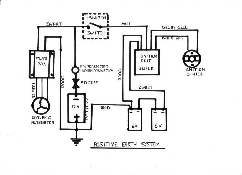
The chassis’ negative should be connected to to the coil’s lower-tension end. This is the ground in the ignition wiring diagram. The high-tension component supplies the spark plugs with positive. The metal body of the coil needs to be connected to the chassis for suppression purposes however it isn’t electrically required. The ignition wiring diagram will also outline the connection of the positive coil’s terminals. Sometimes, a defective ignition coil can be detected with a scan at an auto parts shop.
The black-and-white-striped wire from the harness goes to the negative terminal. The positive terminal receives the other white wire and the black trace. The black wire is connected to the contactbreaker. You can check the connections with a paperclip to take the wires out from the housing. Be sure the terminals aren’t bent.
Accessory terminals
Diagrams of ignition wiring show the various wires utilized to power the vehicle’s various parts. There are usually four color-coded terminals that correspond to each component. The red color is for accessories, yellow is the battery and green is the starter solenoid. The “IGN terminal is used for starting the car, operating the wipers and other functions. The diagram shows how you can connect the ACC and ST terminals to the other components.
The battery is connected to the terminal whose name is BAT. The electrical system cannot start without the battery. In addition, the switch will not begin to turn on. You can refer to your wiring diagram if not sure where the batteries of your car are located. The ignition switch and battery are connected through the accessory terminals. The BAT terminal is connected to the battery.
Some ignition switches feature an independent “accessory” position, where users can manage their outputs without using the ignition. Some customers may prefer to use the auxiliary output in addition to the ignition. For the auxiliary output to be used, plug in the connector with the same shade as the ignition. Then connect it with the ACC end of the switch. Although this is a great feature, there’s one thing you should know. Most ignition switches will have an ACC position if the car is in ACC however they will be at the START position if the car is in IGN.
Gallery of Boyer Ignition Wiring Diagram
Gallery of Boyer Ignition Wiring Diagram


