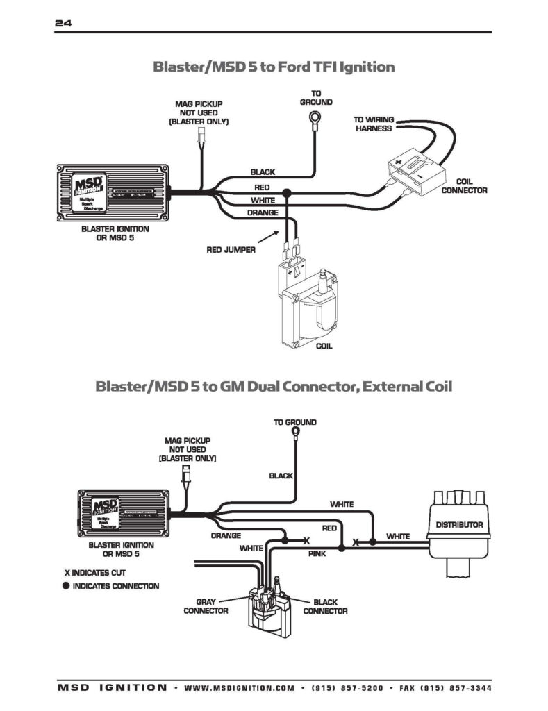
Briggs And Stratton Ignition Coil Wiring Diagram – First, we will take a look at the various kinds of terminals found in the ignition switch. They include terminals for Coil, Ignition Switch, and Accessory. Once we know the purpose of each kind of terminal, we can then identify the various components of the ignition wiring. We will also discuss what functions are available for the Ignition switch and the Coil. Next, we’ll discuss the functions of the Ignition switch as well as Coil.
Terminals for ignition switch
An ignition switch is made up of three switches. These are the ones that supply the battery’s energy to various destinations. The ON/OFF state of the ignition switch is controlled by the first switch, which supplies power to the choke when it’s pulled. Different manufacturers have different color-coding schemes for different conductors. We will cover this in a different article. OMC uses this method. The ignition switch also includes a connector for adding a Tachometer.
While many ignition switch terminals could not be original, the numbers of each may not match the diagram. You should first check the continuity of the wires to see if they are connected to the correct ignition switch. This can be checked using a simple multimeter. When you’re satisfied that all wires are running in good harmony and you are able to connect the new connector. If you have an ignition switch supplied by the manufacturer, the wiring loom is different from that in your car.
Before connecting the ACC outputs to your car’s auxiliary outputs It is essential to be familiar with the fundamentals of these connections. The ACC/IGN terminals function as the default connection on the ignition switch. The START/IGN terminals are connected to the stereo or radio. The ignition switch regulates the engine in your car. The terminals of older vehicles ignition switches are marked by “ACC” as well as ST (for the individual magneto wires).
Terminals for coil
The first step to determine the type of ignition coil is to understand the terms employed. A basic diagram of the wiring will reveal a variety of connections and terminals. Each coil comes with its own operating voltage. To determine the type of coil you’ve got, the first step is to check the voltage at S1, which is the primary terminal. S1 must also go through resistance testing to determine whether it is a Type A or B coil.
The chassis’ negative must be connected to connect the coil’s low-tension side. This is also the ground for the diagram of ignition wiring. The high tension side provides positive directly the spark plugs. The aluminum body of the coil has to be connected to the chassis to prevent it from being smothered, but it isn’t electrically required. A wiring diagram can depict the connection between positive and negative coils. There could be an issue with your ignition coil that is easily identified by scanning it at an auto parts retailer.
The black-and-white-striped wire from the harness goes to the negative terminal. The terminal for the negative is served by the trace in black that’s connected to the white wire. The black wire goes to the contact breaker. You can check the connections with a pencil to pull the wires out from the housing. Make sure the terminals aren’t bent.
Accessory terminals
The diagrams for ignition wiring depict the wires that are used in the power supply of the vehicle. There are typically four color-coded terminals to each component. The red color is for accessories, yellow is the battery and green for the starter solenoid. The “IGN” terminal is used to start the car , and also to operate the wipers, as well as other operating features. This diagram demonstrates how to connect ACC and ST terminals with the rest of the components.
The terminal BAT is where the battery is. Without the battery the electrical system will not begin. Furthermore, the switch won’t start. It is possible to view your wiring diagram to determine where your car’s batteries are placed. The accessory terminals in your car connect to the ignition switch and the battery. The BAT terminal is connected to the battery.
Some ignition switches include an accessory position where users can alter their outputs and manage them without having to turn on the ignition. Customers sometimes want the auxiliary output to be used separately from the ignition. To allow the auxiliary output to be used, connect the connector in the same color as that of the ignition. Then connect it with the ACC end of the switch. While this is an excellent feature, there’s one important difference. The majority of ignition switches are set to operate in the ACC position when the vehicle is in the ACC position, but they’re set to the START position when the car is in the IGN position.
Gallery of Briggs And Stratton Ignition Coil Wiring Diagram
Gallery of Briggs And Stratton Ignition Coil Wiring Diagram


