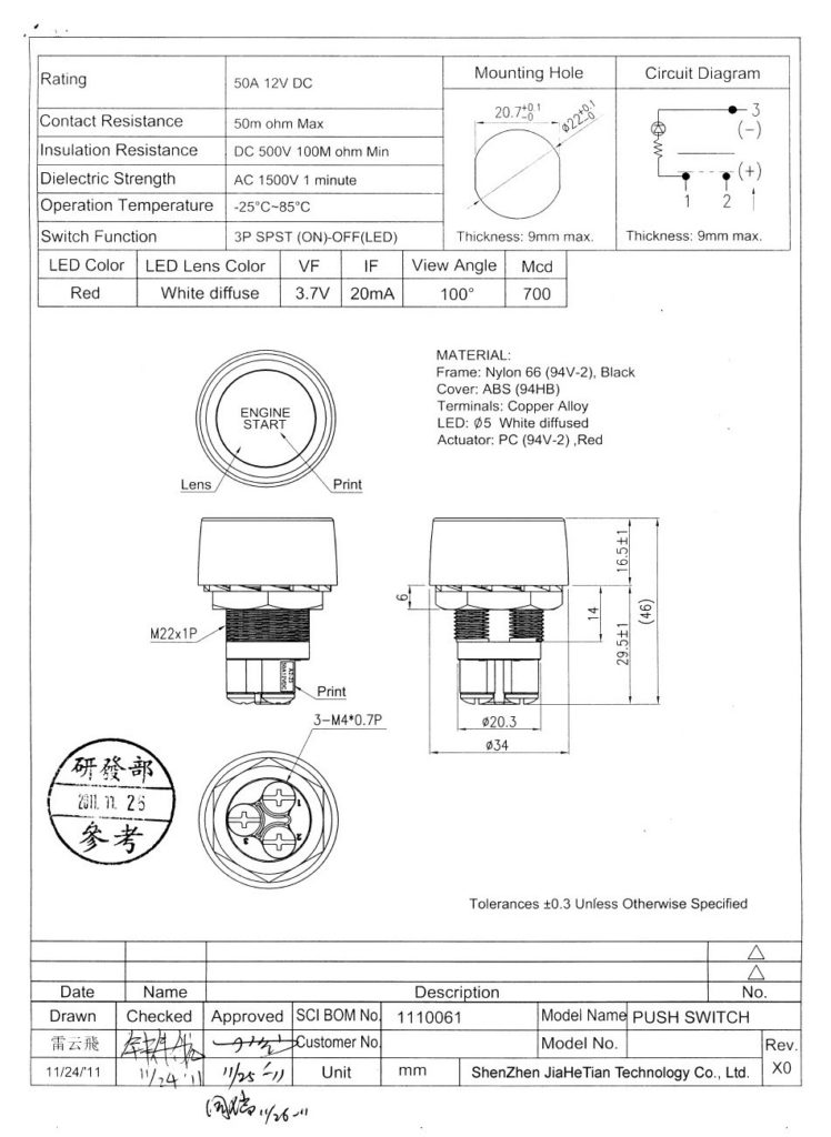
Cambridge Universal Push To Start Ignition Switch Wiring Diagram – Let’s first examine the different types and purposes of the terminals found on the ignition switches. They are the terminals used for Coil, Ignition Switch, and Accessory. After we’ve identified the purpose of these terminals then we can determine the various components in the ignition wiring. We will also cover the roles of both the Ignition Switch and the Coil. We’ll then turn our attention to the accessory terminals.
The ignition switch’s terminals
An ignition switch is comprised of three switches. They feed the battery’s voltage to different places. The first switch provides power to the choke whenever it is pushed. The third is the ignition switch’s ON/OFF position. Different manufacturers have different colour-coding systems that correspond to the conductors. OMC uses this method. A connector is also included in the ignition switch for connecting an to a tachometer.
Although some ignition switch terminals do not appear in their original configuration however, the numbers may not match that of the diagram. To make sure that the wires are connected to the ignition switch you should check their continuity. This can be done using an inexpensive multimeter. When you’re satisfied that the wires are in good continuity and you are able to connect the new connector. If you are using an ignition switch that is supplied by the manufacturer the wiring loom may be distinct from the one that is you have in your car.
In order to connect the ACC outputs to the auxiliary outputs of your vehicle, you have to understand how these two connections work. The ACC terminals as well as the IGN terminals serve as the default connections to the ignition switch. The START and IGN connections are the most important connections for stereo and radio. The ignition switch acts as the engine’s on/off button. Older vehicles are identified with the initials “ACC”, “ST”, (for individual magneto cables) at the ignition switch’s terminals.
Terminals for coil
The first step in determining the type of ignition coil is to know the terms used. You will see several connections and terminals on the basic wiring diagram for ignition, including two primary, as well as two secondary. The coils come with a distinct operating voltage. The initial step in determining which type you’ve got is to check the voltage at S1, the main terminal. S1 must also be subjected to resistance tests to determine if it’s a Type A or B coil.
The negative end of the chassis should be connected to connect the coil’s low-tension side. This is what you see in the diagram of wiring. The high tension part supplies positively directly to the spark plugs. To reduce the noise, the coil’s body metal must be connected with the chassis. It is not required for electrical use. The ignition wiring diagram will also indicate the connection of the positive coil terminals. Sometimes, an inspection at an auto part store can detect a defective ignition wire.
The black-and-white-striped wire from the harness goes to the negative terminal. The negative terminal is served by the black trace joined to the white wire. The black wire connects to the contact breaker. To verify the connection, make use of a paperclip or pencil to lift them out of the plug housing. It’s also crucial to make sure that the terminals aren’t bent.
Accessory terminals
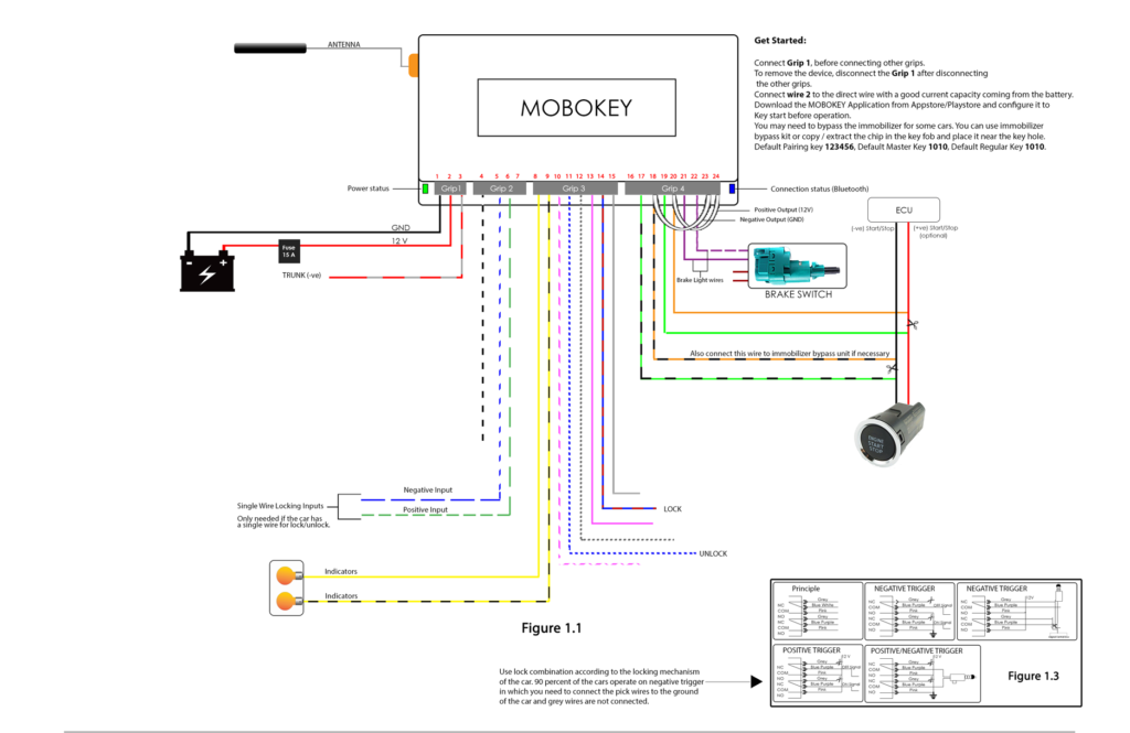
The ignition wiring diagrams illustrate the various wires utilized to power the vehicle’s various components. Typically there are four distinct colored terminals for each part. The red color is for accessories, yellow to the battery and green is the starter solenoid. The “IGN” terminal lets you start the car, control the wipers, or any other operation features. The diagram illustrates the connection to the ACCand ST terminals.
The terminal BAT holds the battery. Without the battery the electrical system can not get started. Also, the switch won’t be able to turn on without the battery. To locate your car’s battery examine the wiring diagram. The accessory terminals on your car are connected to the battery and the ignition switch. The BAT terminal is connected to the battery.
Some ignition switches include an accessory position where users can alter their outputs and manage them without having to turn on the ignition. Some customers may prefer to use the auxiliary output independently of the ignition. Use the secondary output by connecting it to the ACC terminal on your switch with the same colors. This is a great convenience feature, but there is one difference. Many ignition switches can be set to have an ACC position once the car has been moved into the ACC position. They will also be in the START position when the vehicle has entered the IGN position.
Gallery of Cambridge Universal Push To Start Ignition Switch Wiring Diagram
Gallery of Cambridge Universal Push To Start Ignition Switch Wiring Diagram


