Car Ignition Key Wiring Diagram – The first step is to look at the different terminals on the ignition switch. These are the terminals that connect the Ignition, Coil, or Accessory. Once we know the purpose of each terminal, we can then identify the parts of the ignition wiring. We’ll also discuss the roles of both the Ignition Switch and Coil. Then, we will focus on the accessories terminals.
Terminals for the ignition switch
An ignition switch has three switches. They supply the battery’s voltage to many different places. The first switch supplies the choke with power, while the second toggles the state of the switch. Different manufacturers have different color-coding systems to identify different conductors. We will cover this in a separate article. OMC follows this scheme. A connector can be added to the ignition switch in order to connect an electronic tachometer.
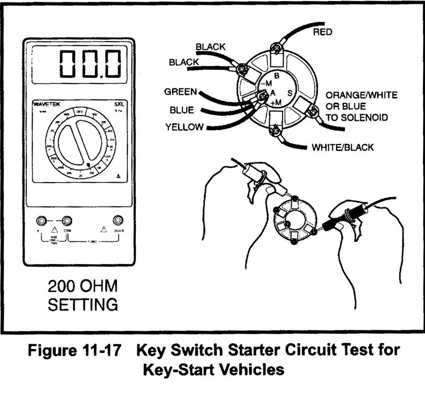
While the majority of the ignition switch terminals are not original, the numbers for each one may not be in line with the diagram. To make sure that your wires are plugged in to the ignition switch, you must verify their continuity. A multimeter is a good tool to test the continuity. After you’re sure that the wires are in good continuity then you can connect the new connector. If your vehicle has an original ignition switch supplied by the factory (or wiring loom), the wiring loom might differ from that of your vehicle.
Understanding how the ACC outputs connect to the auxiliary outputs of your car is vital. The ACC and IGN connectors are the default connections for your ignition switch. Although the START, IGN, and ACC terminals are the primary connections to the radio or stereo, the START/IGN connections are the primary ones. The ignition switch is the one that controls the engine of your car. In older vehicles the terminals of the ignition switch are marked with the alphabets “ACC”, and “ST” (for the individual magnet wires).
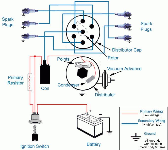
Terminals for coil
To determine the type of ignition coil you need to know the step is to learn the definition of. A simple diagram of the wiring will display a range of terminals and connections, which include two primary terminals and two secondary. You need to determine the kind of coil you have by testing the voltage at the primary terminal, called S1. To determine whether it’s a Type A, C, or B coil you should also test S1’s resistance.
The coil’s low-tension side should be connected to the chassis’s minus. This is what is known as the ground for the wiring for ignition. The high-tension supply delivers positively directly to spark plugs. The aluminum body of the coil needs to be linked to the chassis for suppression but isn’t required. The wiring diagram for the ignition will demonstrate how to connect the terminals of either the positive and negative coils. Sometimes, a defective ignition coil is identified through a scan performed in an auto parts shop.
The black-and-white-striped wire from the harness goes to the negative terminal. Positive terminal gets the white wire that includes a black trace. The black wire connects to the contactbreaker. If you’re not sure about the connections between the two, try using a paper clip to remove them from the plug housing. It’s also crucial to ensure that the terminals don’t bend.
Accessory terminals
Ignition wiring diagrams show the different wires that are utilized to power the vehicle’s various parts. There are usually four different colored terminals for each component. Red is used to indicate accessories, yellow the battery and green the starter solenoid. The “IGN” terminal can be used to start the vehicle and control the wipers, as well as other operating features. The diagram shows how to connect ACC or ST terminals as well as the rest.
The battery is connected to the terminal whose name is BAT. The electrical system is not able to begin without the battery. The switch won’t be able to turn on if there is no battery present. A wiring diagram can show the location of the battery of your car. The accessory terminals of your car connect to the battery and the ignition switch. The BAT terminal is connected with the battery.
Some ignition switches come with a separate “accessory” location, which allows users can manage their outputs without the ignition. In some cases, users may want to use the auxiliary output separately from the ignition. It is possible to use the secondary input by connecting it to the ACC terminal. Although this is a useful feature, there’s one significant difference. The majority of ignition switches are configured to display an ACC status when the car’s at the ACC or START position.
Gallery of Car Ignition Key Wiring Diagram
Gallery of Car Ignition Key Wiring Diagram


