Chevrolet Ignition Switch Wiring Diagram – Let’s begin by examining the different types and functions of the terminals found on the ignition switches. These include the terminals that are for the Ignition switch, Coil, and Accessory. Once we have identified the purpose of these terminals and what they do, we can then be able to identify the various parts of the ignition wiring. We’ll also discuss the functions of both the Ignition Switch and the Coil. We will then discuss the function of the ignition switch and Coil.
The ignition switch’s terminals
There are three separate switches on the ignition switch, and they provide the battery’s voltage to a variety of places. The first switch is utilized to drive the choke by pushing it, and another switch controls the ON/OFF position. Each manufacturer has its unique color-coding system, which we’ll discuss in a subsequent article. OMC utilizes this system. The connector permits the attachment of a speedometer to the ignition switch.
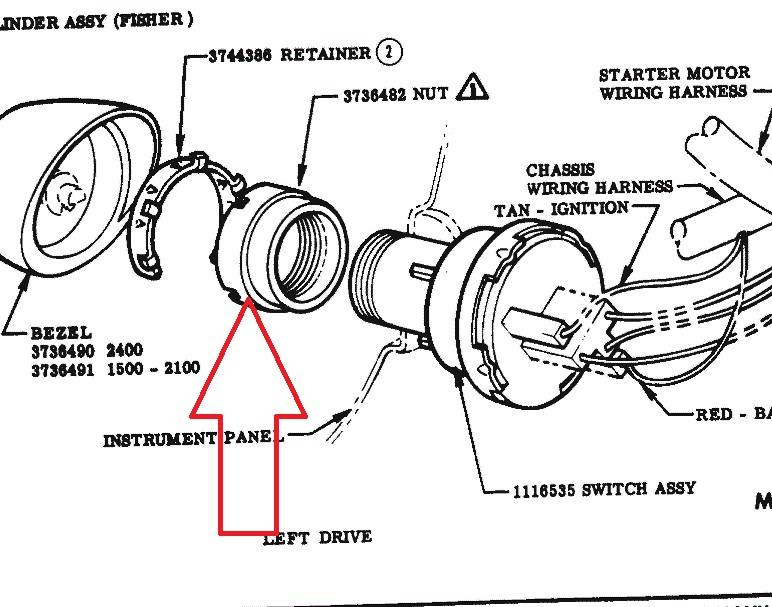
While most ignition switch terminals are not original, the numbers for each may not match the diagram. To make sure that your wires are properly connected to the switch it is recommended to check their continuity. This can be done using a simple multimeter. Once you’re satisfied about the integrity of the wires, then you’ll be able install the new connector. If you are using a factory-supplied ignition switch the wiring loom may be different from the one you have in your car.
In order to connect the ACC outputs to the auxiliary outputs on your vehicle, you have to understand how these two connections work. The ACC and IGN connectors are the default connections for the ignition switch. While the START, IGN, and ACC terminals are primary connections for radios or stereo, the START/IGN terminals are the most important ones. The ignition switch is responsible for turning the car’s engine to and off. Older cars are equipped with ignition switch terminals marked “ACC” or “ST” (for individual magnetowires).
Coil terminals
To figure out the type of ignition coil, the first step is to understand the terms. The diagram of the basic ignition wiring depicts various connections and terminals. There are two primary and secondary connections. Each coil comes with its own operating voltage. To determine what kind of coil you own, the first step is to determine the voltage at the S1 primary terminal. S1 should also undergo resistance testing to determine if it is an A or B coil.
The coil’s low-tension side should be connected at the chassis’ plus. This is what’s called the ground in the diagram of the ignition wiring. The high-tension component supplies the positive power direct to the spark plugs. For suppression purposes, the coil’s body metal must be connected to the chassis. It is not required to use electricity. The wiring diagram for the ignition will explain how to connect the terminals of either the positive and negative coils. Sometimes, a malfunctioning ignition coil can be identified through a scan performed at an auto parts shop.
The black-and-white-striped wire from the harness goes to the negative terminal. Positive terminal receives a second white wire, which is black in its trace. The black wire connects to the contact breaker. You can check the connections using a paperclip to pull the wires out of the housing. Also, make sure to check that the terminals have not been bent.
Accessory terminals
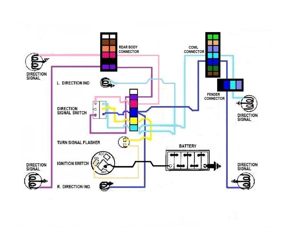
The ignition wiring diagrams show the various wires utilized to power various components. There are usually four colors-coded terminus of each part. The red color is for accessories, yellow to the battery, and green is the starter solenoid. The “IGN” terminal is used to start the car, operate the wipers, as well as other functions. The diagram illustrates how you can connect ACC or ST terminals as well as the rest.
The terminal BAT is where the battery is. The electrical system will not start in the event that the battery isn’t connected. In addition, the switch doesn’t turn on. To find the battery in your car, check your wiring diagram. The accessory terminals of your car are connected to the ignition switch as well as the battery. The BAT terminal is connected to the battery.
Certain ignition switches have a separate “accessory” position, in which users can manage their outputs without using the ignition. Sometimes, customers want to utilize the auxiliary output separate from the ignition. In order for the auxiliary output be used, wire the connector with the same shade as that of the ignition. Then connect it with the ACC end of the switch. Although this is a useful feature, there’s one important difference. A majority of ignition switches feature the ACC position when your vehicle is in the ACC mode and a START mode when you are in IGN.
Gallery of Chevrolet Ignition Switch Wiring Diagram
Gallery of Chevrolet Ignition Switch Wiring Diagram


