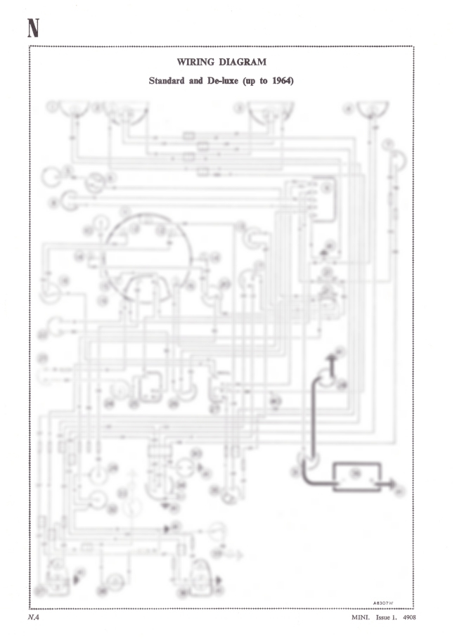
Classic Mini Electronic Ignition Wiring Diagram – Let’s start by looking at the various kinds of terminals that are found on an ignition switch. These terminals serve for the Ignition button, Coil and Accessory. Once we have identified the purpose of these terminals, we will identify the different parts in the ignition wiring. We’ll also discuss the roles of both the Ignition Switch and the Coil. We will then discuss the functions of the ignition switch and Coil.
Terminals for ignition switches
Three switches are located on the ignition switch. Each of these three switches is able to feed the battery’s voltage to several different places. The first switch is utilized to turn on the choke by pushing it, and the third switch is used to control the ON/OFF position. Different manufacturers have different color-coding systems for different conductors. We’ll discuss this in another article. OMC uses this system. A tachometer adapter is installed on the ignition switch that allows the installation of an tachometer.
Although the majority of ignition switch terminals are not original, the numbering for each might not be consistent with the diagram. Before plugging into the ignition switch, be sure to test the continuity. This can be done with an inexpensive multimeter. Once you’re satisfied about the continuity of your wires, you will be able to install the new connector. If your vehicle is equipped with an ignition switch installed the wiring diagram will differ.
Understanding how ACC outputs connect to the auxiliary outputs inside your car is essential. The ACC terminals as well as the IGN terminals are the standard connections for your ignition switch. The START and IGN connections are the most important connections for radio and stereo. The ignition switch acts as the engine’s off/on button. The ignition switch terminals on older cars are labeled with the initials “ACC” and “ST” (for each magneto wires).
Terminals for coil
To determine the type of ignition coil, the first step is to understand the terminology. A simple diagram of the wiring will display a range of terminals and connections, comprising two primary and two secondary. Each coil operates at a specific voltage. The first step in determining which kind of coil you’re dealing with is to test the voltage at S1 or the primary terminal. To determine if it is an A, C, or B coil you must also check the resistance of S1.
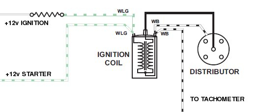
The chassis’ negative end should be connected to connect to the coil’s lower-tension end. This is the wiring diagram you will see on the diagram of wiring. The high-tension component connects the spark plugs to a positive. It is essential for suppression purposes that the body of the coil’s metal be connected to the chassis, however it isn’t essential. It is also possible to see the connections between the positive and the negative coil’s terminals on the ignition wiring diagram. It is possible to find an ignition coil problem that is easily identified by scanning it at the auto parts shop.
The black-and-white-striped wire from the harness goes to the negative terminal. The other white wire is black-colored and goes to the negative terminal. The black wire is connected to the contact breaker. If you’re not sure about the connection between the twowires, use a paper clip to remove them from the plug housing. Also, make sure that the connections are not bent.
Accessory terminals
Diagrams of the ignition wiring illustrate the wiring used to supply power to different parts of the car. Typically there are four color-coded terminals for each component. Red refers to accessories, yellow the battery and green is the starter solenoid. The “IGN terminal allows you to start the car, control the wipers, or any other operation features. The diagram shows the connection to the ACC- and ST terminals.
The terminal BAT is where the battery is. The electrical system won’t start without the battery. The switch will not turn on if there is no battery there. To locate your car’s battery look over your wiring diagram. The accessory terminals of your vehicle are connected to the battery as well as the ignition button. The BAT Terminal is connected to the Battery.
Certain ignition switches come with an additional position in which users can modify their outputs as well as control them without the need to use the ignition. Customers sometimes want the output of the auxiliary to be used separately from the ignition. You can use the auxiliary output by connecting the connector to an ACC terminal on your switch with the same colors. This feature of convenience is fantastic however there’s a difference. The majority of ignition switches are set to have an ACC position when the vehicle is in the ACC position, while they’re in the START position when the car is in the IGN position.
Gallery of Classic Mini Electronic Ignition Wiring Diagram
Gallery of Classic Mini Electronic Ignition Wiring Diagram


