Coil Pack Circuit 3 Pin Ignition Coil Wiring Diagram – First, we will take a look at the different kinds of terminals for the ignition switch. These terminals are used for the Ignition button, Coil and Accessory. After we’ve identified which terminals are used then we can determine the various components of the Coil Pack Circuit 3 Pin Ignition Coil Wiring Diagram. In addition, we will discuss the roles of both the Ignition Switch and Coil. Then, we will concentrate on the accessory terminals.
The ignition switch’s terminals
There are three separate switches in the ignition switch, and they provide the battery’s voltage to a variety of locations. The first one supplies power to the choke whenever it is pushed. The third is the position of the ignition switch’s ON/OFF. Different manufacturers have their own color-coding system for the different conductors, which is explained in a different article. OMC follows the same system. The adapter is attached to the ignition switch that allows for the addition of an Tachometer.
While most ignition switch terminals are duplicated, the numbers might not match the diagram. To ensure that your wires are properly connected to the ignition switch, you must verify their continuity. A multimeter is an excellent tool to test the continuity. After you’ve confirmed the integrity of the wires you can then install the connector. If your vehicle has an original ignition switch supplied by the factory (or a wiring loom), the wiring loom will differ from the one in your vehicle.
To connect the ACC outputs to the auxiliary outputs on your vehicle, you have to understand how these two connections work. The ACC/IGN terminals act as the default connections for the ignition switch. The START/IGN terminals are connected to the radio or stereo. The ignition switch turns the car’s engine on and off. Older cars have the ignition switch terminals labeled “ACC” or “ST” (for individual magnetowires).
Terminals for coil
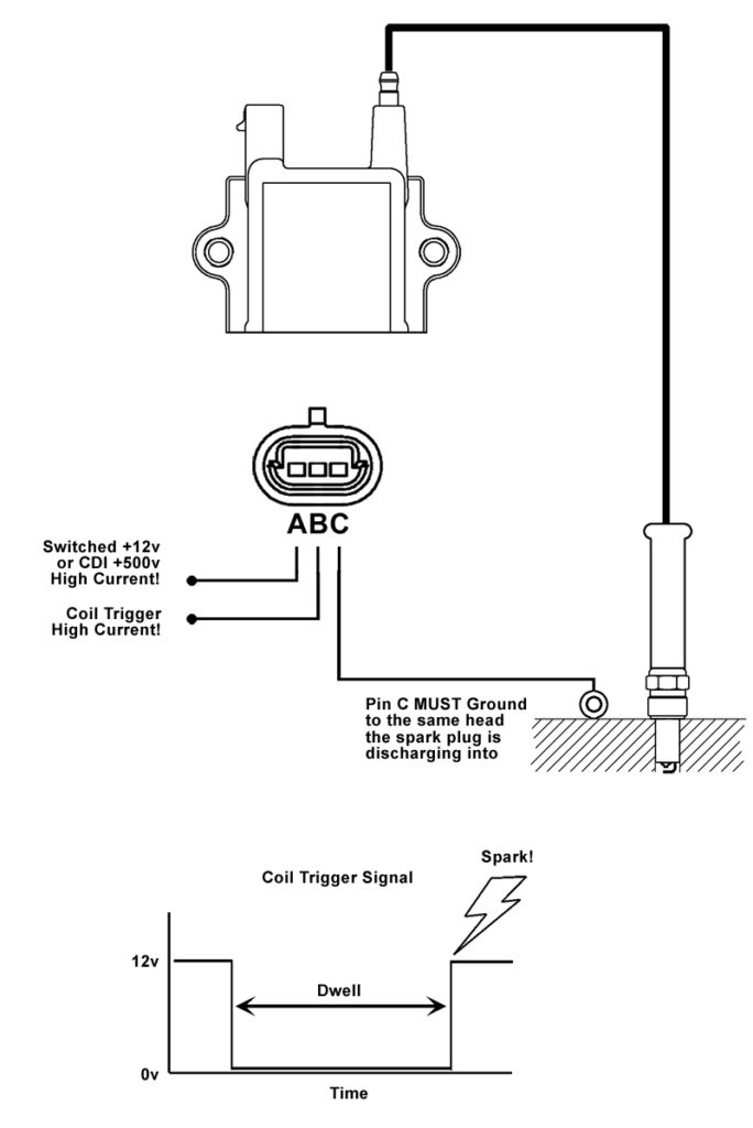
Understanding the terminology used is the first step in determining the kind of ignition coil you need. In a typical ignition wiring diagram there are various terminals and connections, including two primary and two secondary. The coils come with a distinct operating voltage. The initial step to determine which one you have will involve testing the voltage of S1 the main terminal. S1 should also be checked for resistance to determine if the coil is an A, Type B or A coil.
The chassis’ negative must be connected to the low-tension side. This is what’s called the ground on the diagram of ignition wiring. The high-tension supply supplies positive directly to spark plugs. To prevent noise, the coil’s metal body must be connected to chassis. It is not necessary to electrically connect. The wiring diagram will depict the connection between positive and negative coils. You may find an ignition coil problem that can be easily diagnosed by scanning it at an auto parts retailer.
The black-and-white-striped wire from the harness goes to the negative terminal. The white wire has a black color and connects to the terminal opposite. The contact breaker is connected to the black wire. If you’re unsure of the connection between the two, try using an old paper clip to take them from the plug housing. Be sure that you don’t bend the connectors.
Accessory terminals
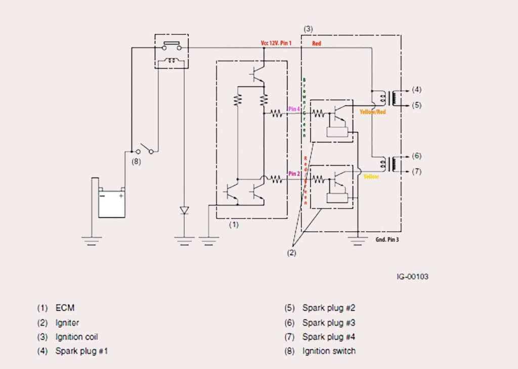
The wiring diagrams of the ignition illustrate the various wires that are used to power various components of the vehicle. Typically there are four colored terminals for each part. To identify accessories, red is for starter solenoid, yellow is for battery, and blue for accessory. The “IGN” terminal allows you to start your car, operate the wipers or other features that operate. The diagram shows the connections of the ACC- and ST terminals.
The battery is attached to the terminal called BAT. The battery is essential to allow the electrical system to begin. The switch will not turn off if the battery isn’t there. The wiring diagram will tell you where to find your car’s battery. The accessory terminals of your car are connected to the battery and the ignition switch. The BAT terminal is connected to the battery.
Certain ignition switches have an accessory position where users can adjust their outputs and control them without the need to use the ignition. Some customers prefer to make use of an additional output that is not connected to the ignition. To make use of the additional output, wire the connector with the same colors as the ignition connecting it to the ACC terminal on the switch. This option is useful however it does have one major differentiator. The majority of ignition switches are designed to show an ACC status when the vehicle is in either the ACC or START position.
Gallery of Coil Pack Circuit 3 Pin Ignition Coil Wiring Diagram
Gallery of Coil Pack Circuit 3 Pin Ignition Coil Wiring Diagram


