Compu Fire Ignition Wiring Diagram – The first step is to examine the various terminals on the ignition switch. These terminals are used for the Ignition button, Coil and Accessory. After we’ve identified the terminals that are utilized and which ones are not, we can identify the different components of the Compu Fire Ignition Wiring Diagram. We will also discuss the functions of the Ignition switch and Coil. After that, we will focus on the accessories terminals.
Terminals for the ignition switch
An ignition switch has three separate switches that feed the battery’s power to various destinations. The first one supplies the choke with power when it is pushed. The third is the switch that controls the ignition’s ON/OFF positions. Different manufacturers use their own color-coding systems for the various conductors, which is documented in another article. OMC utilizes the same system. The ignition switch is also equipped with a connector for adding the tachometer.
Although some ignition switch terminals don’t appear in their original configuration The numbering might not match the diagram. To make sure that your wires are correctly connected to the switch, you should check their continuity. This can be done using an inexpensive multimeter. After you’re happy with the continuity of the wires connect the new connector. If your car has an ignition switch that is installed, the wiring diagram will differ.
Before you can connect the ACC outputs to the auxiliary outputs of your car, it is important to know the fundamentals of these connections. The ACC terminals as well as the IGN terminals serve as the primary connections to the ignition switch. The START and IGN connections are the main connections for stereo and radio. The ignition switch operates the engine’s on/off button. Older cars are identified by the initials “ACC”, “ST”, (for individual magneto cables) on their ignition switch terminals.
Terminals for Coil
The language used to decide the model and type of the ignition coil is the primary thing. There are a variety of connections and terminals within the basic wiring diagram for ignition which includes two primary and two secondary. Each coil is equipped with a distinct operating voltage. To determine the type of coil you’ve got, the first step is to test the voltage at S1, the primary terminal. You should also examine S1 for resistance to identify if it’s a Type A B, C, or coil.
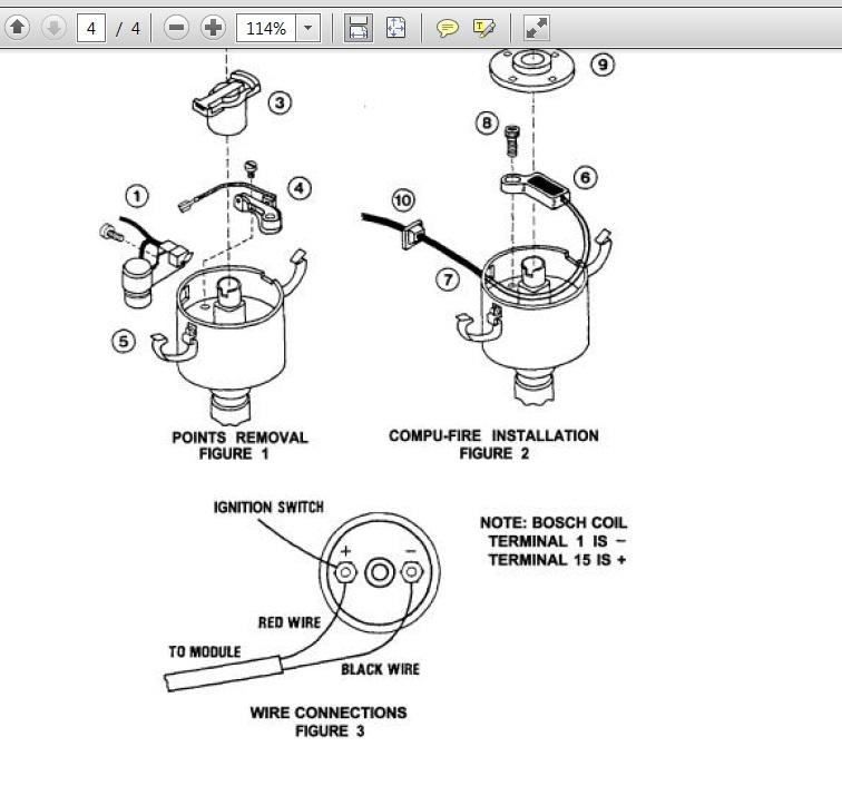
The negative end of the chassis end should be connected to the coil’s low-tension side. This is the ground in the wiring diagram for ignition. The high-tension side supplies the positive power directly to the spark plugs. To reduce the noise, the coil’s metal body must be connected to the chassis. But, it’s not necessary to electrically connect. The diagram of the ignition wiring will also indicate the connections of the positive coil’s terminals. There could be an issue with your ignition coil which can be identified by looking it up at an auto parts store.
The black-and-white-striped wire from the harness goes to the negative terminal. Positive terminal gets the second white wire, which has a black trace. The contact breaker is connected to the black wire. To check the connections, you can use a paperclip or a pencil to remove them of the plug housing. It’s also crucial to make sure the terminals don’t bend.
Accessory terminals
Diagrams of ignition wiring show the different wires used to power various components. Each component has four distinct colored connections. For accessories, red is for starter solenoid, yellow is for battery and blue for accessory. The “IGN terminal is used to start the car, controlling the wipers, and for other functions. The diagram illustrates how you can connect ACC or ST terminals and the rest.
The terminal BAT holds the battery. Without the battery the electrical system will not begin. The switch won’t turn on if there is no battery there. If you’re not sure where your car’s battery is situated, review the wiring diagram of your car to determine where it is. The ignition switch and the battery are connected by the accessory terminals. The BAT terminal is connected to the battery.
Some ignition switches come with an additional position. This lets users access their outputs from another location without having to turn on the ignition. Some customers may prefer to use the auxiliary output independently of the ignition. In order for the auxiliary output be used, connect the connector to the same shade as that of the ignition. Connect it to the ACC end of the switch. Although this is a useful option, there’s an important difference. Many ignition switches can be set to have an ACC location when the car has been moved into the ACC position. They’ll also be in START mode once the vehicle is moved into the IGN position.
Gallery of Compu Fire Ignition Wiring Diagram
Gallery of Compu Fire Ignition Wiring Diagram


