Crane Fireball Hi 6r Ignition Wiring Diagram – The first step is to examine the various terminals used on the ignition switch. These terminals comprise the Ignition switch and Coil as well as the Accessory. Once we have identified the terminals used, we can begin to identify the different components of the Crane Fireball Hi 6r Ignition Wiring Diagram. In addition, we will discuss the function of the Ignition switch, as well as the Coil. Then, we’ll turn our attention to Accessory terminals.
Terminals for the ignition switch
There are three different switches on the ignition switch, and they feed the battery’s voltage to various places. The first switch is utilized to drive the choke by pushing it, and another switch controls the ON/OFF position. Each manufacturer has their individual color-coding system that we’ll discuss in a subsequent article. OMC uses this method. The ignition switch also includes an option to connect an timer.
Although some ignition switch terminals might not be original, the numbering of each one might not match the diagram. Before plugging into the ignition switch make sure to check the continuity. This can be done with a cheap multimeter. Once you are happy with the continuity of the wires, it is time to connect the new connector. The wiring loom of an ignition system switch that is supplied by the manufacturer is distinct.
Understanding how ACC outputs are connected to the other outputs of your car is vital. The ACC terminals as well as the IGN terminals are the primary connections to the ignition switch. The START and IGN connections are the primary connections for radio and stereo. The ignition switch is the engine’s switch to turn off or on. In older vehicles the terminals of the ignition switch are identified with the alphabets “ACC” and “ST” (for the individual magnetic wires).
Terminals for coil
The first step in determining the type of ignition coil is to know the terminology that is used. An ignition wiring diagram will display a range of terminals and connections, comprising two primary and two secondary. The coils come with a distinct operating voltage, and the first method of determining what type you have will involve testing the voltage of S1 the primary terminal. S1 must also go through resistance testing to determine if it are an A or B coil.
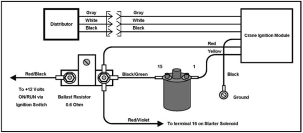
The coil with low tension must be connected at the chassis’ minus. This is what is known as the ground for the wiring for ignition. The high tension side provides positive directly the spark plugs. To reduce the noise, the coil’s metal body must be connected to the chassis. But, it’s not necessary to electrically connect. The ignition wiring diagram will also indicate how to connect the positive coil terminals. Sometimes, a check at an auto parts shop can identify a problem with the ignition wire.
The black-and-white-striped wire from the harness goes to the negative terminal. The terminal for the negative is served by the black trace attached to the white wire. The black wire connects to the contactbreaker. It is possible to remove the black wire from the plug housing using a paper clip If you’re unsure of the connections. It is also important to ensure that the terminals are not bent.
Accessory terminals
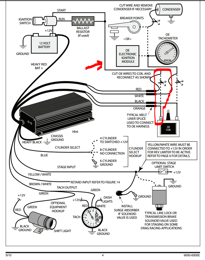
The ignition wiring diagrams illustrate the different wires used to provide power to the various parts of the car. There are generally four terminals with color codes that are connected to the respective component. The red color represents accessories, yellow for the battery and green for the solenoid for starters. The “IGN terminal is used for starting the car, operating the wipers and other functions. The diagram shows the connection of the ACCand ST terminals.
The terminal referred to as BAT is the place where the battery is. The electrical system will not start without the battery. Additionally, the switch will not start without the battery. If you’re not sure of the exact location where the battery in your car is located, you can review your wiring diagram to see the best way to find it. The ignition switch and the battery are connected via accessory terminals. The BAT terminal is connected to the battery.
Certain ignition switches have an accessory position. This lets users connect their outputs to a different location without having to turn on the ignition. Sometimes, users want to utilize an additional output independent of the ignition. You can utilize the auxiliary input by connecting it to the ACC terminal. This is a great convenience feature however, there’s one differentiator. A majority of ignition switches feature the ACC position when the car is in ACC mode, and a START position when the switch is in IGN.
Gallery of Crane Fireball Hi 6r Ignition Wiring Diagram
Gallery of Crane Fireball Hi 6r Ignition Wiring Diagram


