Crane Fireball Hi-6s Ignition Wiring Diagram – We will first examine the various types of terminals found on the ignition switch. They include terminals for the Ignition switch, Coil, and Accessory. After we’ve identified the terminals that are utilized then we can determine the various components of the Crane Fireball Hi-6s Ignition Wiring Diagram. We’ll also be discussing the functions of the Ignition switch, and Coil. We will then turn our attention towards the accessories terminals.
Terminals of ignition switch
There are three separate switches on an ignition switch, which transmit the battery’s current voltage to various destinations. The first one is used to drive the choke by pushing it. Then, the second is for the ON/OFF setting. Each manufacturer has their individual color-coding system that we’ll go over in a separate article. OMC utilizes this method. The connector allows for the attachment of a speedometer to the ignition switch.
While the majority of ignition switch terminals do not have an initial number, they could be equipped with a different number. Before you plug in the ignition switch, ensure that you check the continuity. This can be done with an inexpensive multimeter. After you’re satisfied with the continuity of the wires it is time to connect the new connector. The wiring loom used for the ignition switch factory-supplied will be different than the one you have in your vehicle.
First, understand the differences between ACC and the auxiliary outputs. The ACC and IGN connectors are the standard connections for your ignition switch. The START, IGN, and ACC terminals are the main connections for radios or stereo, the START/IGN terminals are the main ones. The ignition switch controls the car’s engine. Older cars are identified by the letters “ACC”, “ST”, (for individual magneto cables) at the ignition switch terminals.
Terminals for coil
Understanding the terms is the first step towards knowing what type of ignition coil you’ve got. An ignition wiring diagram will reveal a variety of connections and terminals, comprising two primary and two secondary. Each coil has an operating voltage. The first step to determine which kind of coil you’re using is to examine the voltage at S1 or the primary terminal. S1 should also be tested for resistance to determine whether it’s a Type B, B or an A coil.
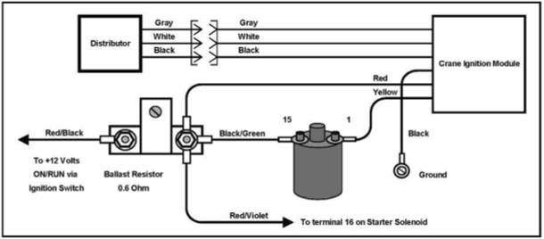
The chassis’ negative should be connected to connect to the coil’s lower-tension end. This is what’s called the ground on the ignition wiring diagram. The high tension side supplies positive directly the spark plugs. It is essential for the purpose of suppression that the metallic body of the coil is connected to its chassis, however it isn’t essential. There are also connections of the positive and the negative coil terminals on the ignition wiring diagram. In certain instances scanning your local auto parts store will be able to diagnose defective ignition coils.
The black-and-white-striped wire from the harness goes to the negative terminal. Positive terminal gets the second white wire, which is black in its trace. The black wire connects to the contactbreaker. You can check the connections with a pencil to take the wires out from the housing. You should also check to ensure that the terminals are not bent.
Accessory Terminals
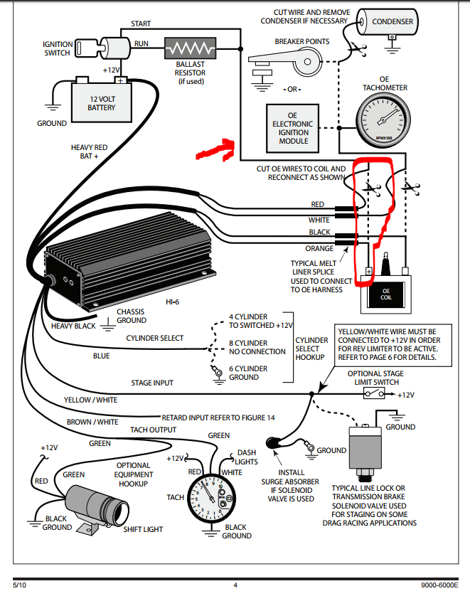
Diagrams of ignition wiring illustrate the wires used to power various parts of the car. In general there are four distinct colored terminals for each part. The red color is used for accessories, yellow is for the battery, and green is the starter solenoid. The “IGN terminal” is used to power the wipers and other operating functions. The diagram demonstrates how to connect the ACC and ST terminals to the rest of the components.
The terminal referred to as BAT is the location where the battery is. The electrical system will not start when the battery isn’t connected. The switch won’t be able to turn on if the battery isn’t present. To find the battery in your car examine the wiring diagram. The ignition switch and the battery are connected by the accessory terminals. The BAT connector is connected to your battery.
Certain ignition switches have an accessory setting where users can alter their outputs and manage them without needing to use the ignition. Customers may want to use the auxiliary output separately from the ignition. Make use of the additional output by connecting it to the ACC terminal on the switch with the same colors. Although this is a fantastic option, there’s a thing you need to know. Most ignition switches are set to operate in the ACC position when the vehicle is in the ACC position, while they’re in the START position when the car is in the IGN position.
Gallery of Crane Fireball Hi-6s Ignition Wiring Diagram
Gallery of Crane Fireball Hi-6s Ignition Wiring Diagram


