Crane Hi 4 Ignition Wiring Diagram – First, we will take a look at the different kinds of terminals on the ignition switch. These terminals are used for the Ignition button, Coil and Accessory. Once we know the terminals that are utilized then we can determine the various components of the Crane Hi 4 Ignition Wiring Diagram. We’ll also go over the function of the Ignition switch and Coil. Following that, we will discuss the Accessory Terminals.
Terminals for ignition switches

An ignition switch is comprised of three switches. They feed the voltage of the battery to many different locations. The first switch supplies power to the choke when pushed, and the second is the position of the ignition switch’s ON/OFF. Different manufacturers use their own color-coding systems for the various conductors, that is described in a separate article. OMC utilizes this approach. An additional connector is included inside the ignition switch for attaching an tachometer.
While most ignition switch terminals are not authentic, the numbering of each one may not be in line with the diagram. You should first check the electrical continuity to ensure that they are connected to the ignition switch in the correct way. This can be accomplished using a simple multimeter. After you’re happy with the integrity of your wires, you will be able install the new connector. If you are using an ignition switch that is supplied by the manufacturer the wiring loom may be different from the one in your car.
To connect the ACC outputs to the auxiliary outputs on your car, you’ll need to understand the way these two connections function. The ACC and IGN connectors are the standard connections of the ignition switch. The START, IGN, and ACC terminals are primary connections for radios or stereo, the START/IGN terminals are the primary ones. The ignition switch switches the car’s engine ON and OFF. Older vehicles have ignition switch terminals marked “ACC” or “ST” (for individual magnetowires).
Terminals for coil
The first step in determining the type of ignition coil is to know the terms that is used. The diagram of the basic ignition wiring shows a number different connections and terminals. There are two primary and secondary connections. Each coil has an operating voltage. The first step to determine which kind of coil you’re using is to examine the voltage of S1 or the primary terminal. To determine if it is a Type A, C, or B coil, you must also test the resistance on S1’s.
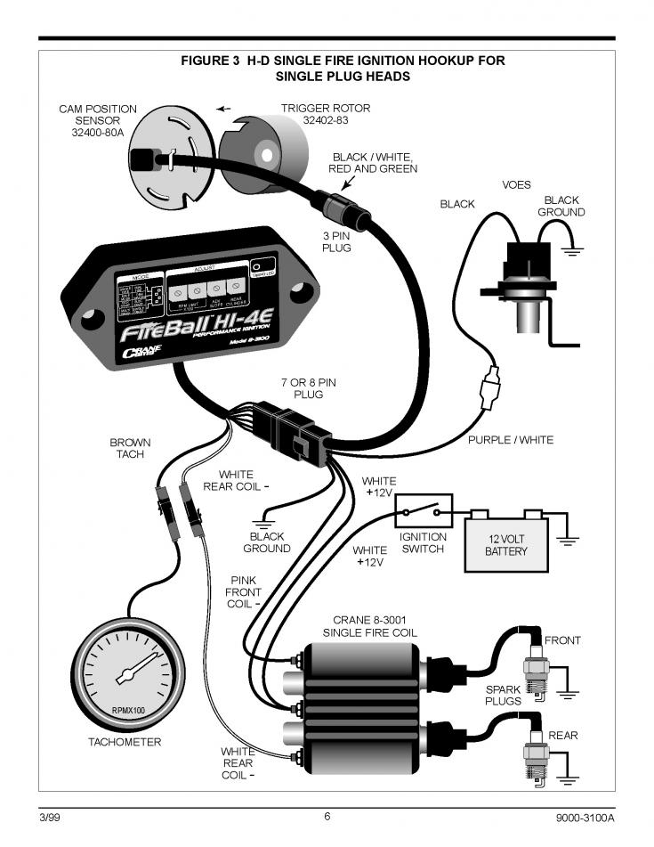
The coil’s low-tension component must be connected to the chassis’ positive. This is what’s called the ground in the diagram of the ignition wiring. The high-tension part supplies the spark plugs with positive. To reduce the noise, the coil’s body metal is required to be connected to the chassis. This is not necessary for electrical use. The ignition wiring diagram will also demonstrate the connections between the positive and negative coil terminals. You may find an ignition coil problem that is easily identified by scanning it at an auto parts retailer.
The black-and-white-striped wire from the harness goes to the negative terminal. The terminal for the negative is served by the black trace connected to the white wire. The black wire is connected to the contact breaker. To check the connection, use a paperclip or a pencil to remove them of the plug housing. Check that you don’t bend the connectors.
Accessory terminals
The ignition wiring diagrams show the various wires utilized for powering the various components. There are generally four terminals with color codes that are connected to the respective component. To identify accessories, red stands the starter solenoid’s color, blue for battery, and blue for accessories. The “IGN” terminal can be used to start the car, turn on the wipers and other features. The diagram shows the connection of the ACCas well as ST terminals.
The terminal BAT connects the battery to the charger. The battery is essential to allow the electrical system to get started. Furthermore the switch isn’t turned on. It is possible to view your wiring diagram to determine the location of your car’s batteries. placed. The accessory terminals of your car are connected with the battery and the ignition button. The BAT connector connects to your battery.
Some ignition switches feature an “accessory” position that allows users to control their outputs , without needing to turn on the ignition. Sometimes, customers want to use an auxiliary output independent of the ignition. In order for the auxiliary output be used, connect the connector to the same color as that of the ignition. Connect it to the ACC end of the switch. While this is an excellent feature, there is one crucial distinction. A lot of ignition switches can be configured to be in an ACC position when the vehicle has moved into the ACC position. They also will be in START mode when the vehicle has moved into the IGN position.
Gallery of Crane Hi 4 Ignition Wiring Diagram

Gallery of Crane Hi 4 Ignition Wiring Diagram


