Crane Ignition Wiring Diagram – First, we will examine the different types of terminals that are used on the ignition switch. They are terminals that are used for Coil, Ignition Switch, and Accessory. Once we have identified what these terminals are then we can identify the different parts in the ignition wiring. We’ll also go over the roles of the Ignition switch as well as the Coil. After that we will move on to the Accessory Terminals.
Terminals for ignition switches
The ignition switch consists of three different switches. These are the ones that supply the battery’s energy to various destinations. The first switch provides power to the choke when pushed, and the second is the position of the ignition switch’s ON/OFF. Different manufacturers have distinct color-coding systems that correspond to the conductors. OMC uses this method. The ignition switch comes with an adapter for the addition of a tachometer.
Although most ignition switch terminals can be duplicated, the number may not be consistent with the diagram. Before you plug in the ignition switch, be sure to test the continuity. This can be checked using a cheap multimeter. After you’re sure that all wires are in good continuity then you can connect the new connector. If your car has an ignition switch installed, the wiring diagram will differ.
Understanding how the ACC outputs are connected to the auxiliary outputs in your car is essential. The ACC and IGN terminals are the default connection on your ignition switch. the START and IGN terminals are the primary connections for radio and stereo. The ignition switch is the one that controls the engine of your car. Older cars have the ignition switch terminals marked “ACC” or “ST” (for individual magnetowires).
Terminals for coil
Understanding the terminology is the first step towards finding out what kind of ignition coil you own. In a basic ignition wiring diagram there are several different connections and terminals, such as two primary and two secondary. Each coil has a specific operating voltage. To determine what kind of coil you have, the first step is to determine the voltage at the S1 primary terminal. S1 must also be inspected for resistance in order to identify whether it’s an A, Type B or an A coil.
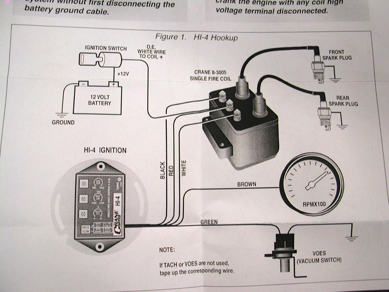
The negative end of the chassis end should be connected to the coil’s low-tension side. It is also the ground for an ignition wiring diagram. The high-tension side provides positive direct to the sparkplugs. To prevent noise the body of the coil must be connected to the chassis. It is not necessary to connect the coil electrically. The diagram of the ignition wiring will also indicate the connections of the positive coil’s terminals. Sometimes, a visit to an auto part store can identify a problem with the ignition wire.
The black-and-white-striped wire from the harness goes to the negative terminal. The white wire is black and goes to the negative terminal. The black wire is connected to the contact breaker. To confirm the connection, make use of a paperclip or pencil to remove them of the plug housing. Be sure the terminals aren’t bent.
Accessory terminals
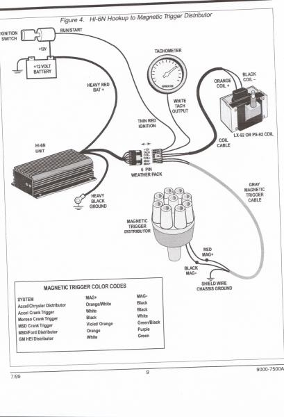
Diagrams of ignition wiring show the wires used to provide power to various components of the car. There are typically four terminals with color codes that are connected to each component. Red stands for accessories, yellow is for the battery, and green for the starter solenoid. The “IGN terminal” is used to run the wipers, as well as other operating features. The diagram illustrates the connection between the ACCand ST terminals.
The terminal BAT is the connection to the battery. The electrical system won’t start without the battery. A dead battery could make the switch not come on. If you don’t know the location of your car’s battery situated, you can review your wiring diagram to see the best way to find it. The accessory terminals in your car are connected to the battery and the ignition button. The BAT terminal is connected to the battery.
Certain ignition switches have an independent “accessory” location, which allows users can control their outputs without using the ignition. Some customers may prefer to use the auxiliary output in addition to the ignition. For the auxiliary output to be used, plug in the connector to the same color as the ignition. Connect it to the ACC end of the switch. This convenience feature is great however, there’s one difference. Most ignition switches are configured to be in an ACC position when the vehicle is in the ACC position, whereas they’re set to the START position when the vehicle is in the IGN position.
Gallery of Crane Ignition Wiring Diagram
Gallery of Crane Ignition Wiring Diagram


