Cub Cadet Ignition Wiring Diagram – Let’s first examine the different types and purposes of the terminals that are found in the ignition switches. These include the terminals for the Ignition switch, Coil, and Accessory. Once we have established the purpose of these terminals are for then we can discover the various components of the Cub Cadet Ignition Wiring Diagram. We’ll also discuss the functions as well as the Coil. We’ll then turn our attention on the accessory terminals.
Terminals for ignition switch
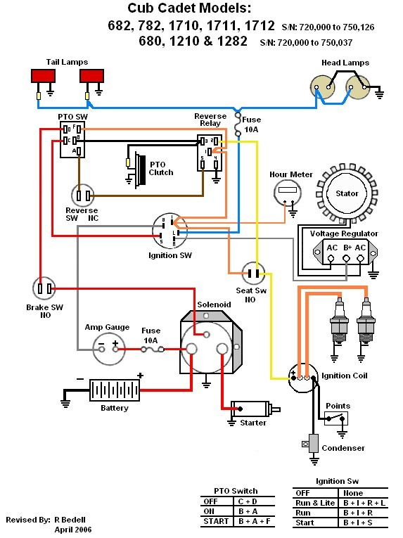
Three switches are located on an ignition switch. Each of these switches feeds the battery’s voltage to various destinations. The first is utilized to drive the choke by pushing it. Then, another switch controls the ON/OFF position. Different manufacturers employ various color codes for the different conductors. This is discussed in another article. OMC utilizes this method. A connector is also included in the ignition switch for connecting the Tachometer.
Even though some of the ignition switch terminals could not be authentic, the numbering of each may not be in line with the diagram. To ensure that your wires are correctly connected to the ignition switch, you should check their continuity. You can do this with an inexpensive multimeter. Once you’re satisfied with the quality of the connection then you can connect the new connector. If your vehicle has an original ignition switch supplied by the factory (or a wiring loom) the wiring loom may differ from that in your vehicle.
For connecting the ACC outputs to the auxiliary outputs of your car, you’ll need to understand how these two connections work. The ACC/IGN terminals function as the default connections on the ignition switch. The START/IGN connections connect to the stereo or radio. The ignition switch is the one that turns the engine of your car on and off. Older cars are identified with the alphabets “ACC”, “ST”, (for individual magneto cables) at the ignition switch terminals.
Terminals for coil
To figure out the type of ignition coil you need to know the step is to know the definition of. The diagram of the basic ignition wiring shows a number different connections and terminals. There are two primary and one secondary. Each coil has a specific operating voltage. To determine which type of coil you’ve got first, you need to determine the voltage at S1, which is the primary terminal. S1 should be checked for resistance to determine if the coil is Type A, B, and/or C.
The lower-tension side of the coil must be connected to the chassis’ negative. This is what’s called the ground in the ignition wiring diagram. The high tension side supplies positive power directly to the spark plugs. It is necessary for the purpose of suppression that the body of the coil’s metal be connected to its chassis however, it is not necessary. The wiring diagram for ignition will also indicate how to connect the positive coil terminals. Sometimes, a defective ignition coil can be detected with a scan at an auto repair shop.
The black-and-white-striped wire from the harness goes to the negative terminal. The other white wire has a black color and connects to the negative terminal. The contact breaker is connected to the black wire. If you’re not sure about the connections between the twowires, use a paper clip to remove them from the housing of the plug. Make sure that the terminals don’t bend.
Accessory Terminals
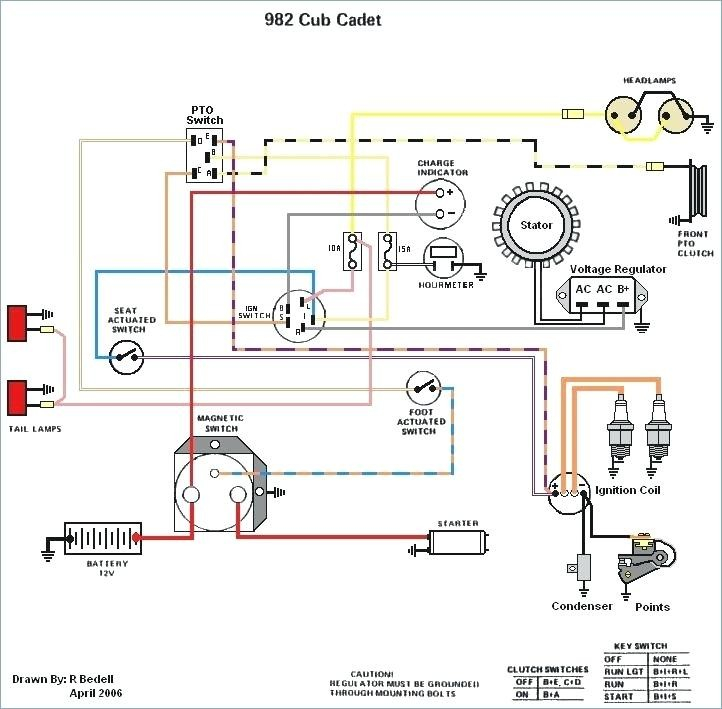
Diagrams of the ignition wiring show the wires that provide power to various components of the vehicle. There are typically four color-coded terminals to each component. Red stands for accessories, yellow is for the battery, and green for the starter solenoid. The “IGN” terminal is used to turn on the car and operate the wipers as well as other operational functions. The below diagram illustrates how to connect the ACC terminal as well as the ST terminals to other components.
The terminal BAT is the connection to the battery. The electrical system is not able to start without the battery. Also, the switch won’t be able to turn on without the battery. You may refer to the wiring diagram if uncertain about where the car’s batteries are. The accessory terminals on your vehicle are connected to the battery and the ignition switch. The BAT connector is connected to your battery.
Some ignition switches come with an additional position. It allows users to connect their outputs to a different location without the ignition. Some customers prefer to utilize an additional output independent of the ignition. Make use of the additional output by connecting the connector to the ACC terminal on the switch with the same colors. While this is a convenient feature, there’s one important difference. The majority of ignition switches have an ACC position if the car is in the ACC however they’ll be at the START position if the vehicle is IGN.
Gallery of Cub Cadet Ignition Wiring Diagram
Gallery of Cub Cadet Ignition Wiring Diagram


