Denso Ignition Coil Wiring Diagram – Let’s begin by looking at the various types terminals found in an ignition switch. These terminals serve for the Ignition button, Coil and Accessory. Once we have established what these types of terminals are for then we can discover the various components of the Denso Ignition Coil Wiring Diagram. Then, we will discuss the functions as well as the Coil. After that we will move on to the Accessory Terminals.
Terminals for ignition switch
An ignition switch has three different switches that direct the battery’s current to different locations. The first switch supplies power to the choke whenever pushed, and the second is the switch that controls the ignition’s ON/OFF positions. Different manufacturers have different color-coding schemes to identify different conductors. We will cover this in another article. OMC follows this system. Connectors can be connected to the ignition switch in order to add a digital tachometer.
Although the majority of ignition switch terminals are duplicated, the numbers might not match the diagram. Before you plug into the ignition switch ensure that you check the continuity. A cheap multimeter can aid in this. After you’ve confirmed that the wires are in good condition, you can then install the connector. If your car has an installed ignition switch, the wiring diagram will differ.
It is important to understand how the ACC outputs and auxiliary outputs function to connect them. The ACC, IGN and START terminals are the primary connections to the ignition switch. They also function as the main connections to the radio and stereo. The ignition switch is responsible for turning the engine of your car on and off. Older cars are identified by the letters “ACC”, “ST”, (for individual magneto cables) at the ignition switch’s terminals.
Coil terminals
To figure out the type of ignition coil, the first step is to understand the terminology. In a simple ignition wiring diagram, you will see a number of different terminals and connections, including two primary and two secondary. You must determine the kind of coil you are using by testing the voltage on the primary terminal, S1. You should also test S1 for resistance in order to determine if it’s an A B, C, or coil.
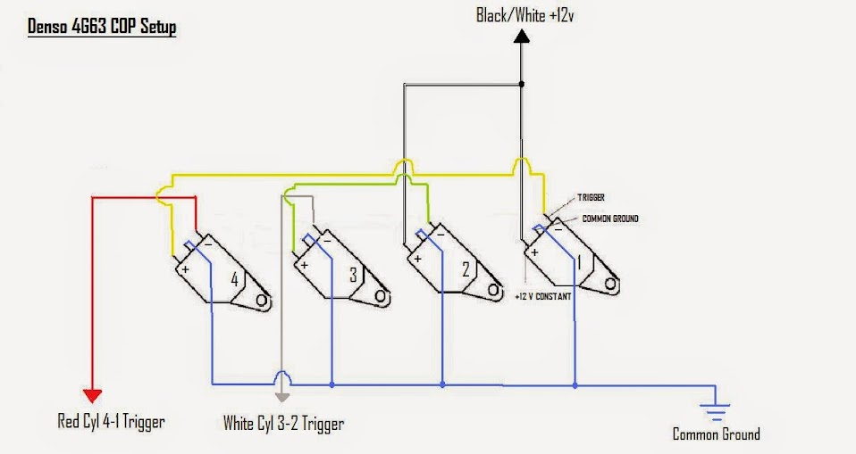
The chassis’ negative end should be connected to connect to the coil’s lower-tension end. This is the ground on the wiring diagram for ignition. The high-tension end is a positive connection to the sparkplugs. To reduce the noise, the coil’s metal body must be connected to the chassis. But, it’s not necessary to connect the coil electrically. A wiring diagram can illustrate the connection between the positive and negative coils. In certain cases scanning the local auto parts store will be able to diagnose the malfunctioning ignition coils.
The black-and-white-striped wire from the harness goes to the negative terminal. The white wire also has a black trace on it and connects to the positive terminal. The black wire is connected to the contact breaker. To verify the connections between the two wires use a paperclip and remove them out of the housing. Check that the terminals aren’t bent.
Accessory terminals
Diagrams of ignition wiring show the various wires utilized for powering the different components. There are typically four color-coded terminals that correspond to the component. Accessories are red, the battery is yellow and the starter solenoid green. The “IGN” terminal is used to turn on the car , and also to operate the wipers as well as other operational functions. The below diagram shows how to connect the ACC terminal and ST terminals to other components.
The terminal referred to as BAT is where the battery is connected. The battery is essential to allow the electrical system to get started. A dead battery could make the switch not turn on. If you’re not sure the location of your car’s battery located, you can review your wiring diagram to figure out the best way to find it. The ignition switch is connected to the battery of your car. The BAT terminal is connected to the battery.
Some ignition switches offer the option of an “accessory position” which allows users to adjust their outputs independently of the ignition. Sometimes, customers wish to use the auxiliary output separately from the ignition. Use the additional output by connecting the connector to an ACC terminal on your switch using the same colors. This feature is convenient, but it has one significant difference. Most ignition switches are designed to show an ACC status when the car’s in the ACC or START position.
Gallery of Denso Ignition Coil Wiring Diagram
Gallery of Denso Ignition Coil Wiring Diagram


