Dodge Ignition Control Module Wiring Diagram – In the beginning, we’ll look at the different types of terminals on the ignition switch. The terminals are the Ignition switch, the Coil and the Accessory. After we’ve identified what these terminals are then we can determine the various components in the ignition wiring. In addition, we will discuss the function of the Ignition switch and Coil. The next step is to focus to the accessory terminals.
Terminals for ignition switch
An ignition switch is composed of three switches. They are responsible for feeding the battery’s power to several locations. The first one supplies power to the choke whenever it is pushed. The second is the ignition switch’s ON/OFF position. Different manufacturers have different color-coding systems that correspond to the conductors. OMC uses this method. A connector can be added to the ignition switch in order to connect an electronic Tachometer.
While the majority of the ignition switch terminals aren’t original, the numbers for each may not match the diagram. The first step is to check the continuity of all the wires to make sure they’re properly connected to the ignition switches. A multimeter is a great tool to test the continuity. After you have verified the continuity of the wires you are able to connect the connector. The wiring loom in the ignition system switch supplied by the manufacturer is different.
You must first understand the ways in which the ACC outputs and the auxiliary outputs function in order to connect them. The ACC, IGN and START terminals are the primary connections to the ignition switch. They are also the primary connections to the radio and stereo. The ignition switch switches the engine of your car ON and off. Older vehicles are identified with the initials “ACC”, “ST”, (for individual magneto cables) on their ignition switch terminals.
Terminals for Coil
The first step in determining the type of ignition coil is to understand the terminology employed. In a simple ignition wiring diagram you’ll see several different terminals and connections, including two primary and two secondary. Each coil operates at a specific voltage. The first step in determining which kind you’re using is to examine the voltage of S1 or the primary terminal. You should also examine S1 for resistance to determine if it’s a Type A or B coil.
The chassis’ negative end should be connected to the coil’s low-tension end. This is what is known as the ground for the ignition wiring. The high-tension supply delivers the spark plugs with positive electricity directly. The aluminum body of the coil has to be connected to the chassis to prevent it from being smothered but isn’t required. The wiring diagram for the ignition will explain how to connect the two terminals of the positive or negative coils. Sometimes, a malfunctioning ignition coil can be identified with a scan at an auto repair shop.
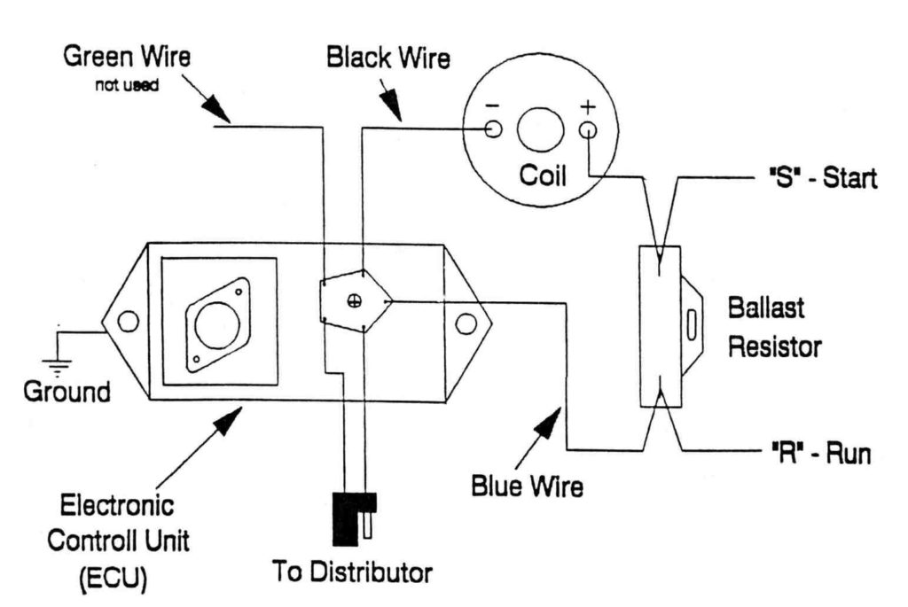
The black-and-white-striped wire from the harness goes to the negative terminal. The other white wire is black with a trace on it, and it connects to the positive terminal. The black wire is connected to the contact breaker. If you’re unsure of the connections between the two, try using an old paper clip to take them from the housing of the plug. It is also important to make sure the terminals do not bend.
Accessory terminals
Diagrams of ignition wiring show the wires that are used in the vehicle’s power supply. There are usually four colored terminus lines for each component. Red stands for accessories, yellow is for the battery and green for the solenoid for starters. The “IGN” terminal allows you to start the car, manage the wipers, or any other features that operate. The diagram shows how to connect the ACC and ST terminals to the rest of the components.
The terminal BAT connects the battery to the charger. Without the battery, the electrical system does not start. Additionally, the switch won’t start. If you’re not sure of the exact location where the battery in your car is located, you can look at the wiring diagram of your car to determine how to locate it. The accessory terminals in your car are connected with the battery and the ignition button. The BAT terminal is connected to the battery.
Some ignition switches come with an additional “accessory” location, which allows users can control their outputs without the ignition. Sometimes, a customer wants to use the auxiliary output separate from the ignition. For the auxiliary output to be used, plug in the connector in the same color as that of the ignition. Then connect it with the ACC end of the switch. This is a useful feature, however there’s an important difference. The majority of ignition switches have an ACC position when the vehicle is in the ACC however, they’ll be in the START position when the vehicle is in IGN.
Gallery of Dodge Ignition Control Module Wiring Diagram
Gallery of Dodge Ignition Control Module Wiring Diagram


