Dyna S Ignition Wiring Diagram – First, we will take a look at the different kinds of terminals that are used on the ignition switch. These are the terminals for the Ignition, Coil, or Accessory. Once we know what these types of terminals are used for, we will proceed to determine the various parts of the Dyna S Ignition Wiring Diagram. We’ll also go over the roles of the Ignition switch, as well as the Coil. Then, we’ll turn our attention to Accessory terminals.
The ignition switch’s terminals
Three switches are located in an ignition switch. Each of these three switches transmits the battery’s current to a variety of locations. The first switch supplies power to the choke whenever pushed, and the second is the ignition switch’s ON/OFF position. Different manufacturers use their own color-coding systems for the various conductors, that is described in a separate article. OMC utilizes this system. The adapter is attached to the ignition switch to allow for the addition of a Tachometer.
While most ignition switch terminals may not be original, the numbering for each might not be consistent with the diagram. Examine the continuity of the wires first to make sure they’re connected correctly to the ignition switch. A cheap multimeter can assist you in this. After you’re happy with the integrity of your wires, you’ll be able install the new connector. If your car has an original ignition switch supplied by the factory (or wiring loom), the wiring loom may differ from that of the car.
Before you can connect the ACC outputs to your car’s auxiliary outputs, it is important to know the fundamentals of these connections. The ACC terminals and IGN terminals function as the standard connections for the ignition switch. The START and IGN connections are the most important connections for radio and stereo. The ignition switch controls the car’s engine. The terminals of the ignition switch on older cars are identified with the alphabets “ACC” and “ST” (for each magneto wires).
Coil terminals
The terminology used to determine the kind and model of the ignition coil is the primary thing. A basic ignition wiring layout will reveal a variety of terminals and connections. Each coil has an operating voltage. The first step to determine the kind of coil you have is to check the voltage on S1, or the primary terminal. S1 should also undergo resistance testing to determine whether it are a Type A or B coil.
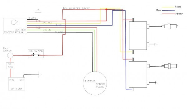
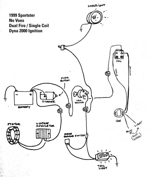
The chassis’ negative must be connected to connect the coil’s low-tension side. This is the ground on the wiring diagram for ignition. The high-tension end provides positive direct to the sparkplugs. For suppression purposes the coil’s metal body is required to be connected to the chassis. This is not necessary to use electricity. The diagram for the ignition wiring will also show you the connections between the negative and positive coil’s terminals. It is possible to find an issue with the ignition coil that is easily identified by scanning it in the auto parts shop.
The black-and-white-striped wire from the harness goes to the negative terminal. The negative terminal is served by the trace in black that’s connected to the white wire. The black wire connects to the contact breaker. It is possible to remove the black wire from the housing of the plug using a paper clip in case you are uncertain about the connection. Be sure that you don’t bend the connectors.
Accessory terminals
Diagrams of ignition wiring depict the wires used in the vehicle’s power supply. There are generally four color-coded terminals to each component. To identify accessories, red is the starter solenoid’s color, yellow is for battery, and blue for accessory. The “IGN terminal” is used to power the wipers along with other operational functions. The diagram shows the connections of the ACC- and ST terminals.
The terminal BAT connects the battery to the charger. Without the battery the electrical system can not get started. The switch won’t be able to turn on if there is no battery present. You can refer to your wiring diagram if unsure where your car’s batteries are. The ignition switch is linked to the car’s battery. The BAT connector is connected to your battery.
Some ignition switches feature an “accessory” setting that allows users to control their outputs without having to use the ignition. Customers sometimes want the auxiliary output to be operated independently of the ignition. In order to use the auxiliary output, connect the connector with the same colors as the ignition connecting it to the ACC terminal on the switch. While this is a convenient feature, there’s one significant difference. Many ignition switches can be configured to be in an ACC position once the car has moved into the ACC position. They also will be in the START mode once the vehicle is entered the IGN position.
Gallery of Dyna S Ignition Wiring Diagram
Gallery of Dyna S Ignition Wiring Diagram


