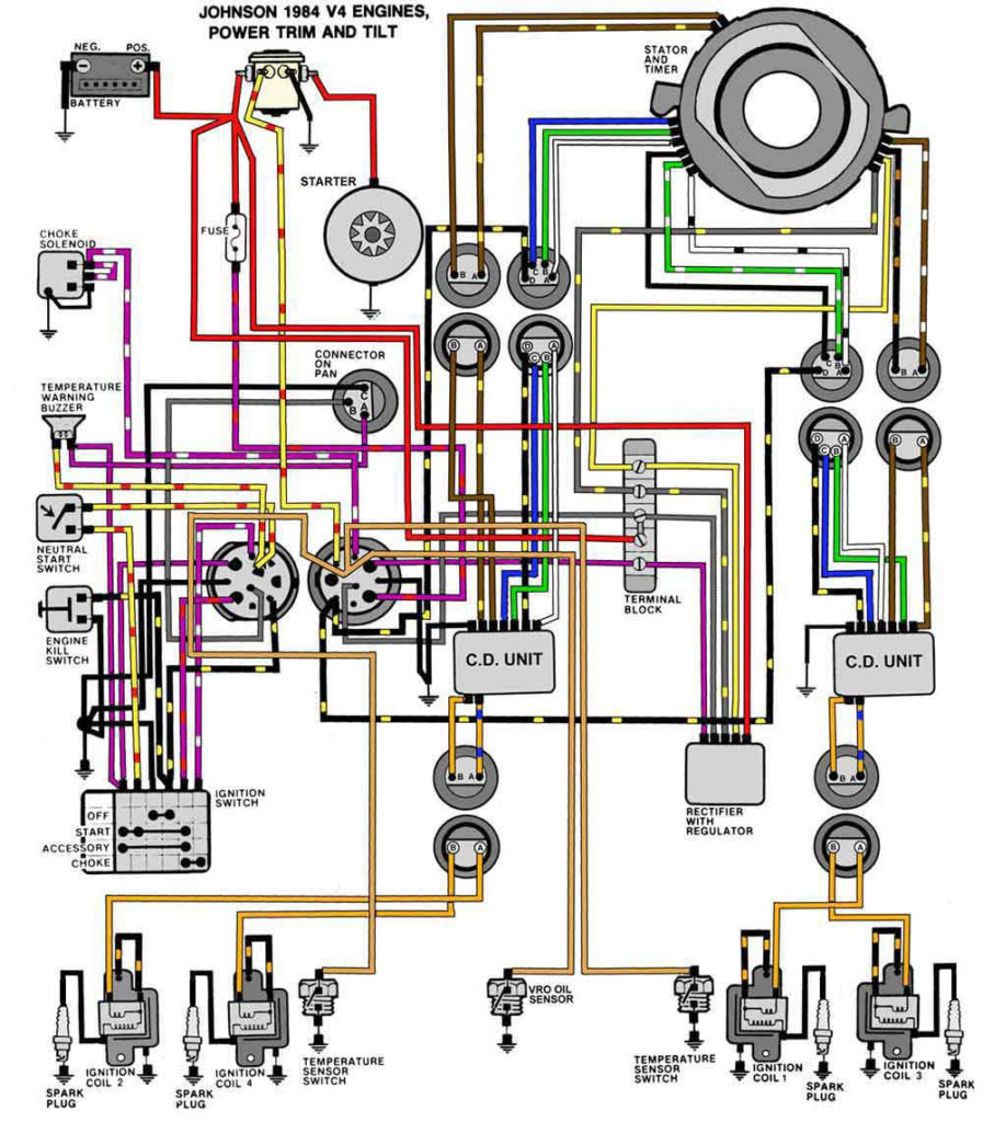
Evinrude Ignition Wiring Diagram – We’ll begin by looking at the different types of terminals on an ignition switch. These include the terminals that are for the Ignition switch, Coil, and Accessory. Once we know what these terminals do then we can be able to identify the various parts of the ignition wiring. We’ll also be discussing the roles of the Ignition switch, and Coil. Then, we’ll talk about the roles of the Ignition switch and Coil.
Terminals for ignition switch
There are three separate switches on an ignition switch that provide the battery’s voltage to various locations. The ON/OFF position of the ignition switch is controlled by the first switch, which provides power to the choke when it’s pushed. Each manufacturer has their own color-coding system, which we will discuss in another article. OMC uses this procedure. The adapter is attached to the ignition switch that allows the addition of the tachometer.
Although most ignition switch terminals are duplicated, the numbers may not be in line with the diagram. Before plugging into the ignition switch, ensure that you check the continuity. This can be accomplished using a simple multimeter. After you have verified that the wires are in good condition, you can then install the connector. If your vehicle is equipped with an ignition switch installed the wiring diagram may differ.
For connecting the ACC outputs to the auxiliary outputs on your vehicle, you have to first understand how these two connections work. The ACC, IGN and START terminals are the primary connections to the ignition switch. They also serve as the primary connections to your radio and stereo. The ignition switch regulates the engine in your car. The terminals of older cars’ ignition switches are labeled by “ACC” as well as ST (for the individual magneto wires).
Terminals for coil
The first step in determining the type of ignition coil is to comprehend the terms employed. An ignition wiring diagram will display a range of terminals and connections, including two primary and two secondaries. The operating voltage of every coil is different. This is why it is crucial to test the voltage at the S1 (primary terminal). S1 must also be inspected for resistance in order to identify whether it’s a Type B, B, or A coil.
The low-tension coil side must be connected to the chassis’ minus. This is what you see in the diagram of wiring. The high tension side supplies positively directly to the spark plugs. The aluminum body of the coil has to be linked to the chassis for suppression but isn’t required. The wiring diagram will illustrate the connection between the positive and negative coils. In certain cases, a scan at the local auto parts store can help you identify the malfunctioning ignition coils.
The black-and-white-striped wire from the harness goes to the negative terminal. The positive terminal receives the other white wire with an trace of black. The black wire is connected to the contact breaker. To check the connections, you can make use of a paperclip or pencil to pull them out from the plug housing. You should also check to ensure that the terminals are not bent.
Accessory terminals
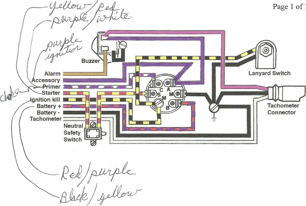
The ignition wiring diagrams show the different wires used to power the various components. There are usually four different colors of terminals connected to each part. Red is for accessories, yellow is for the battery, and green is for the solenoid for starters. The “IGN” terminal is used to start the vehicle, controlling the wipers and various other functions. The diagram illustrates how you can connect ACC or ST terminals, and other.
The terminal BAT connects the battery to the charger. The electrical system cannot start without the battery. A dead battery could make the switch not turn on. The wiring diagram will inform the location of the battery in your car. The accessory terminals in your vehicle connect to the battery as well as the ignition switch. The BAT connector connects to your battery.
Some ignition switches have the “accessory” setting that permits users to regulate their outputs without needing to turn on the ignition. Users may wish to utilize the auxiliary output separately from the ignition. Make use of the auxiliary output by connecting it to an ACC terminal on your switch that has the same color. This is a convenient feature, but it has one significant distinction. Most ignition switches come with the ACC position when your car is in the ACC mode, and a START position when the switch is in IGN.
Gallery of Evinrude Ignition Wiring Diagram
Gallery of Evinrude Ignition Wiring Diagram


