Exmark Lazer Z Ignition Switch Wiring Diagram – Let’s start by looking at different kinds of terminals that are found in an ignition switch. These include the terminals that are for the Ignition switch, Coil, and Accessory. After we’ve identified the terminals used then we can recognize the various parts of the Exmark Lazer Z Ignition Switch Wiring Diagram. We’ll also discuss the different functions of the Ignition Switch and the Coil. After that, we’ll turn our attention to Accessory terminals.
Terminals for ignition switches

An ignition switch is comprised of three switches. They feed the voltage of the battery to different locations. The first one is used to power the choke through pushing it, and the third switch is used to control the ON/OFF position. Different manufacturers utilize their own color-coding method for the various conductors, that is described in a separate article. OMC follows this method. The ignition switch comes with an option to connect an Tachometer.
Although the majority of ignition switch terminals do not come in original form however, the numbers may not be in line with the diagram. To ensure that your wires are properly plugged in to the switch it is recommended to check their continuity. This can be done with a multimeter that is inexpensive. Once you are satisfied with the continuity of the wires, install the new connector. The wiring loom used in the ignition system switch supplied by the manufacturer is distinct.
In order to connect the ACC outputs to the auxiliary outputs on your car, you’ll need to understand the way these two connections function. The ACC, IGN and START terminals are the default connection to the ignition switch. They are also the main connections to the radio and stereo. The ignition switch controls the car’s engine. The terminals for the ignition switch on older cars are identified with the initials “ACC” as well as “ST” (for individual magneto wires).
Terminals for coil
Understanding the terms that is used is the initial step in finding out the right type of ignition coil. The fundamental diagram of ignition wiring depicts various connections and terminals. There are two primary and one secondary. It is essential to identify the type of coil that you are using by testing the voltage at the primary terminal S1. S1 should also undergo resistance testing to determine if it’s a Type A or B coil.
The negative of the chassis must be connected to the side of low-tension. This is what you find in the diagram of wiring. The high-tension part connects the spark plugs to a positive. The body of the coil has to connect to the chassis for suppression purposes but is not electrically required. A wiring diagram can also illustrate the connection between the positive and negative coils. Sometimes, a check at an auto parts shop can detect a defective ignition wire.
The black-and-white-striped wire from the harness goes to the negative terminal. The negative terminal is served by the trace in black that’s attached to the white wire. The black wire is connected to the contact breaker. If you’re not certain about the connections between both, you can use an old paper clip to take them from the housing of the plug. It is also important to make sure that the terminals don’t bend.
Accessory terminals
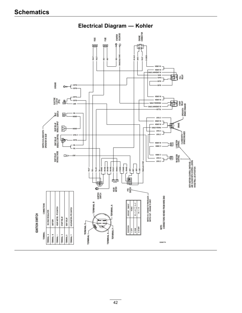
Diagrams of the ignition wiring show the wires used to power various parts of the car. There are generally four colors-coded terminus of each part. The red color is used for accessories, yellow is for the battery, while green is the solenoid for starters. The “IGN” terminal can be used to start the car , and also to operate the wipers as well as other operational features. The following diagram shows how to connect the ACC terminal as well as the ST terminals to other components.
The terminal BAT holds the battery. The electrical system will not start in the event that the battery isn’t connected. Also, the switch won’t turn on without the battery. You can refer to your wiring diagram if unsure where your car’s batteries are located. The accessory terminals in your car connect to the ignition switch and the battery. The BAT terminal is connected to the battery.
Certain ignition switches have an additional position in which users can alter their outputs and manage them without needing to use the ignition. Sometimes, customers would like an auxiliary output that can be used separately from the ignition. It is possible to use the additional input by connecting it to the ACC terminal. While this is a convenient feature, there is one significant difference. Most ignition switches are set up to display an ACC status when the vehicle is at the ACC or START positions.
Gallery of Exmark Lazer Z Ignition Switch Wiring Diagram
Gallery of Exmark Lazer Z Ignition Switch Wiring Diagram


