Ford 12 Volt Ignition Coil Wiring Diagram – The first step is to examine the different types of terminals for the ignition switch. These are the terminals that connect the Ignition, Coil, or Accessory. Once we understand the function of each kind of terminal, it is possible to determine the components of the ignition wiring. In addition, we will discuss the roles of both the Ignition Switch and Coil. We’ll then turn our attention to the accessory terminals.
The terminals of the ignition switch
An ignition switch is made up of three different switches. These are the ones that supply the battery’s power to several destinations. The ON/OFF position of the switch that controls the ignition is managed by the second switch, which delivers power to the choke when it’s pushed. Different manufacturers use different colors for different conductors. This is explained in a separate article. OMC employs this system. The connector permits the connection of a speedometer to the ignition switch.
Although the majority of ignition switch terminals don’t have an original number, they may have a different one. Check the continuity of all the wires to ensure that they are properly plugged into the ignition switches. You can check this using an inexpensive multimeter. After you’re satisfied with the connection then you can connect the new connector. If your vehicle has an original factory-supplied ignition switch (or wiring loom), the wiring loom may differ from the one in your car.
In order to connect the ACC outputs to the auxiliary outputs of your car, you need to understand the way these two connections function. The ACC and IGN connectors are the standard connections for your ignition switch. The START, IGN, and ACC terminals are primary connections for radios or stereo, the START/IGN connections are the most important ones. The ignition switch is responsible for turning the car’s engine on and off. The terminals for the ignition switch on older cars are labeled with the initials “ACC” and “ST” (for individual magneto wires).
Terminals for coil
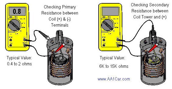
Understanding the terminology is the first step towards knowing what type of ignition coil you have. In a simple ignition wiring diagram there are various connections and terminals, which include two primary and two secondary. The coils have a specific operating voltage, and the first step to determine which one you have will involve testing the voltage at S1, the main terminal. S1 should also undergo resistance tests to determine if it is an A or B coil.
The chassis’ negative must be connected to connect the coil’s low-tension end. This is exactly what you can see on the wiring diagram. The high-tension part supplies the spark plugs with positive. For suppression purposes, the coil’s metal body must be connected to chassis. It is not necessary to electrically connect. The wiring diagram will depict the connection between positive and negative coils. You may find an ignition coil problem that can be easily diagnosed by scanning it at an auto parts retailer.
The black-and-white-striped wire from the harness goes to the negative terminal. The positive terminal receives the other white wire and the trace of black. The black wire connects to the contact breaker. To test the connections between the two wires employ a paperclip to remove them off the housing. Make sure you don’t bend the connectors.
Accessory terminals
The ignition wiring diagrams illustrate the various wires utilized to power the vehicle’s various components. Typically there are four distinct colors-coded terminals that are used for each component. To identify accessories, red is for starter solenoid, yellow is for battery and blue for accessories. The “IGN terminal” is used to run the wipers, as well as other operating features. The diagram illustrates the connection to the ACCas well as ST terminals.
The terminal BAT holds the battery. The battery is essential to allow the electrical system to start. The switch will not turn off if the battery isn’t there. To find the battery in your car, check your wiring diagram. The ignition switch is linked to the car’s battery. The BAT connector is connected to your battery.
Some ignition switches come with an additional “accessory” position, in which users can manage their outputs without the ignition. Customers sometimes want the output of the auxiliary to be operated independently of the ignition. You can use the secondary output by connecting the connector to the ACC terminal on the switch that has the same color. This is a useful option, but there’s an important distinction. Some ignition switches are configured to be in an ACC position once the car has moved into the ACC position. They’ll also be in START mode once the vehicle is entered the IGN position.
Gallery of Ford 12 Volt Ignition Coil Wiring Diagram
Gallery of Ford 12 Volt Ignition Coil Wiring Diagram


